Cycle parameters – HEIDENHAIN iTNC 530 (340 49x-05) Cycle programming User Manual
Page 110
110
Canned Cycles: Tapping / Thread Milling
4.4 T
A
PPING WITH CHIP BREAK
ING (Cy
c
le 209, DIN/ISO: G209)
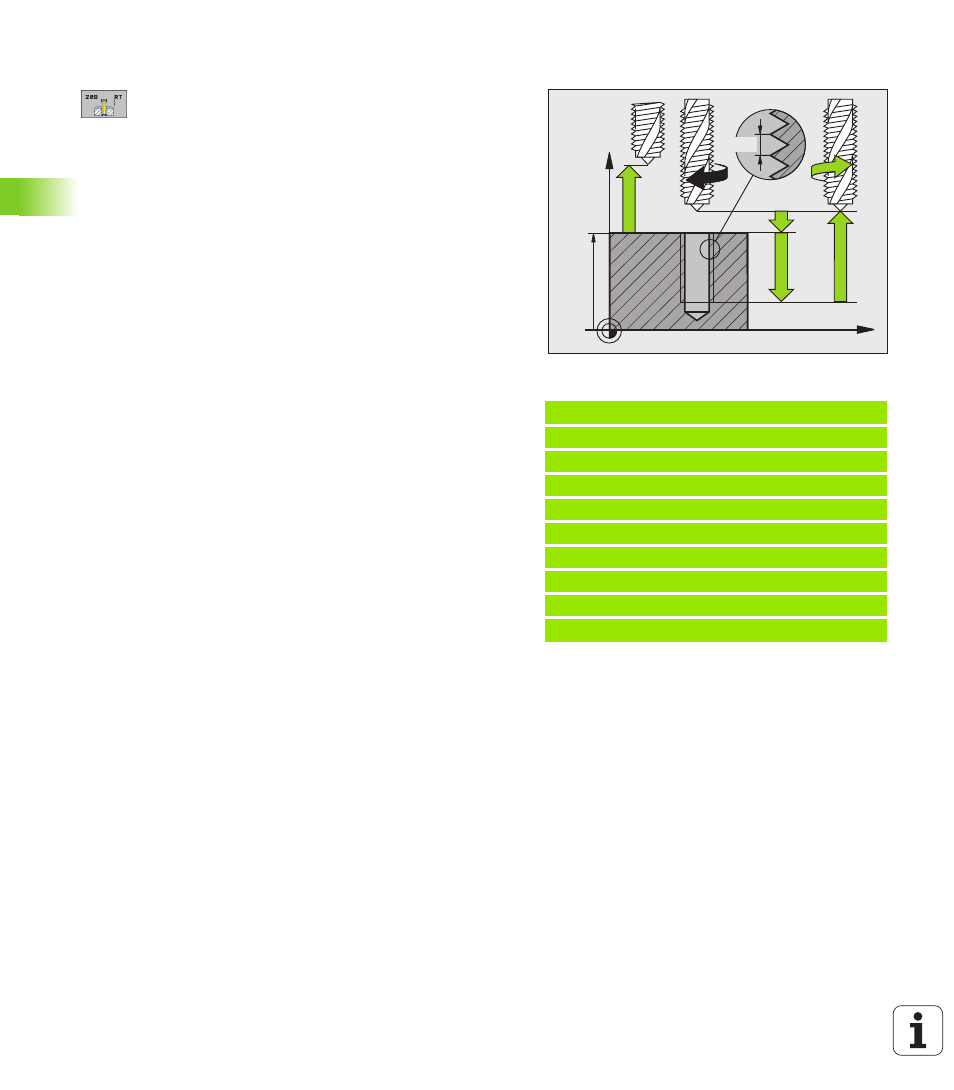
Cycle parameters
U
Setup clearance
Q200 (incremental): Distance
between tool tip (at starting position) and workpiece
surface. Input range 0 to 99999.9999, alternatively
PREDEF
U
Thread depth
Q201 (incremental): Distance between
workpiece surface and end of thread. Input range: -
99999.9999 to 99999.9999
U
Pitch
Q239
Pitch of the thread. The algebraic sign differentiates
between right-hand and left-hand threads:
+ = right-hand thread
– = left-hand thread
Input range -99.9999 to 99.9999
U
Workpiece surface coordinate
Q203 (absolute):
Coordinate of the workpiece surface. Input range:
-99999.9999 to 99999.9999
U
2nd setup clearance
Q204 (incremental): Coordinate
in the spindle axis at which no collision between tool
and workpiece (fixtures) can occur. Input range 0 to
99999.9999, alternatively PREDEF
U
Infeed depth for chip breaking
Q257 (incremental):
Depth at which TNC carries out chip breaking. Input
range: 0 to 99999.9999
U
Retraction rate for chip breaking
Q256: The TNC
multiplies the pitch Q239 by the programmed value
and retracts the tool by the calculated value during
chip breaking. If you enter Q256 = 0, the TNC retracts
the tool completely from the hole (to the setup
clearance) for chip breaking. Input range: 0.1000 to
99999.9999
U
Angle for spindle orientation
Q336 (absolute):
Angle at which the TNC positions the tool before
machining the thread. This allows you to regroove the
thread, if required. Input range –360.0000 to
360.0000.
U
RPM factor for retraction
Q403: Factor by which
the TNC increases the spindle speed—and therefore
also the retraction feed rate—when retracting from
the drill hole. Input range 0.0001 to 10, rpm is
increased at most to the maximum speed of the
active gear range.
Retracting after a program interruption
If you interrupt program run during thread cutting with the machine
stop button, the TNC will display the MANUAL OPERATION soft key.
If you press the MANUAL OPERATION key, you can retract the tool
under program control. Simply press the positive axis direction button
of the active spindle axis.
Example: NC blocks
26 CYCL DEF 209 TAPPING W/ CHIP BRKG
Q200=2
;SETUP CLEARANCE
Q201=-20
;DEPTH
Q239=+1
;PITCH
Q203=+25
;SURFACE COORDINATE
Q204=50
;2ND SETUP CLEARANCE
Q257=5
;DEPTH FOR CHIP BRKNG
Q256=+25
;DIST. FOR CHIP BRKNG
Q336=50
;ANGLE OF SPINDLE
Q403=1.5
;RPM FACTOR
Z
X
Q203
Q204
Q200
Q201
Q239