3 polar reference plane (cycle 1, din/iso), Cycle run, Please note while programming – HEIDENHAIN iTNC 530 (340 49x-05) Cycle programming User Manual
Page 391: Cycle parameters
HEIDENHAIN iTNC 530
391
16.3 POLAR REFERENCE PLANE (Cy
c
le 1, DIN/ISO)
16.3 POLAR REFERENCE PLANE
(Cycle 1, DIN/ISO)
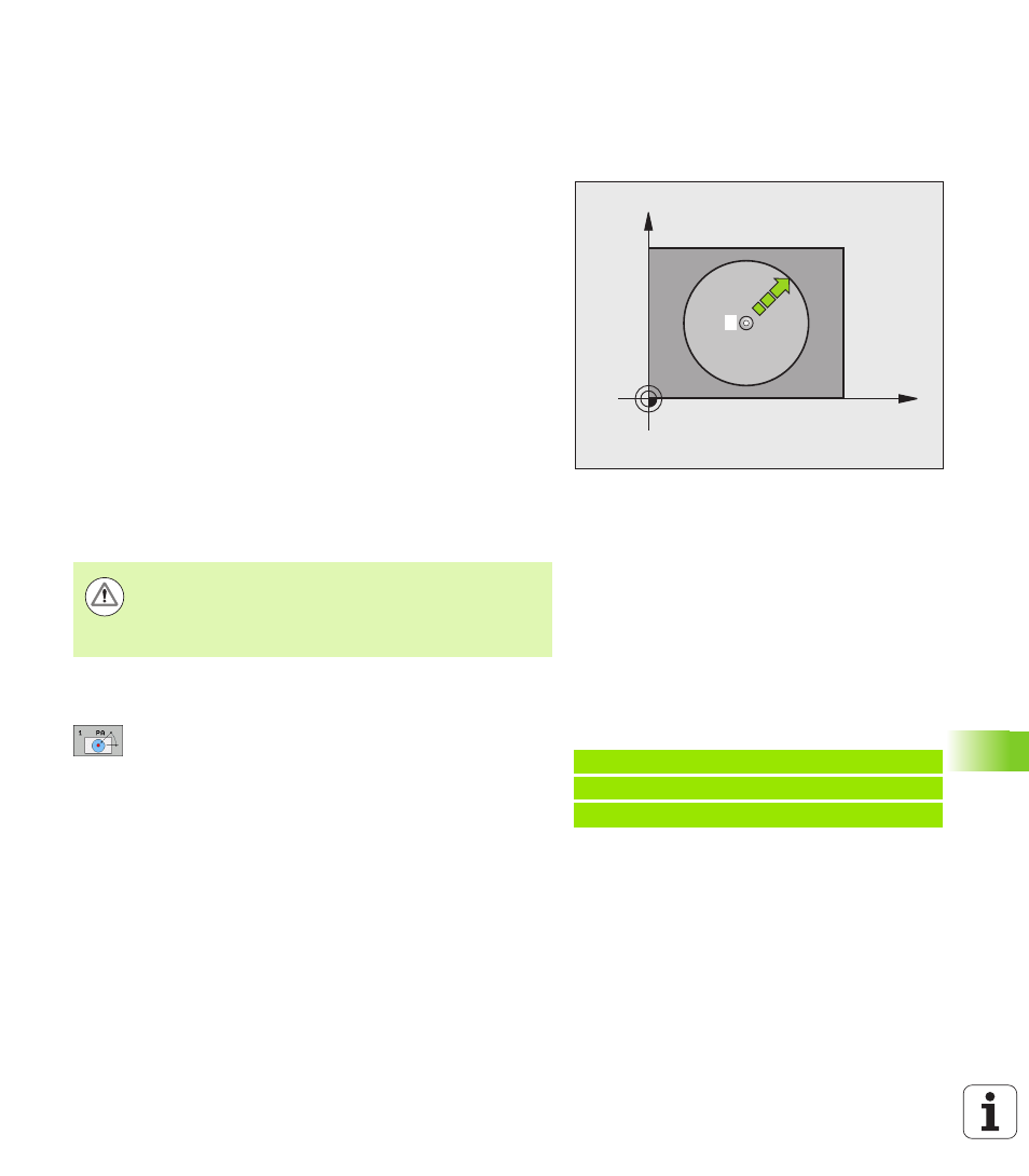
Cycle run
Touch Probe Cycle 1 measures any position on the workpiece in any
direction.
1
The touch probe moves at rapid traverse (value from MP6150 or
MP6361) to the starting position
1
programmed in the cycle.
2
Then the touch probe approaches the workpiece at the feed rate
assigned in MP6120 or MP6360. During probing the TNC moves
simultaneously in 2 axes (depending on the probing angle). The
scanning direction is defined by the polar angle entered in the
cycle.
3
After the TNC has saved the position, the probe returns to the
starting point. The TNC also stores the coordinates of the touch
probe position at the time of the triggering signal in parameters
Q115 to Q119.
Please note while programming:
Cycle parameters
U
Probing axis:
Enter the probing axis with the axis
selection keys or ASCII keyboard. Confirm your entry
with the ENT key. Input range: X, Y or Z
U
Probing angle:
Angle, measured from the probing
axis, at which the touch probe is to move. Input
range: -180.0000 to 180.0000
U
Nominal position value:
Use the axis selection keys
or the ASCII keyboard to enter all coordinates of the
nominal pre-positioning point values for the touch
probe. Input range: -99999.9999 to 99999.9999
U
To conclude the input, press the ENT key.
X
Y
1
Danger of collision!
Pre-position the touch probe in order to avoid a collision
when the programmed pre-positioning point is
approached.
Example: NC blocks
67 TCH PROBE 1.0 POLAR DATUM PLANE
68 TCH PROBE 1.1 X ANGLE: +30
69 TCH PROBE 1.2 X+5 Y+0 Z-5