Cycle parameters – HEIDENHAIN iTNC 530 (340 49x-05) Cycle programming User Manual
Page 244
244
Canned Cycles: Multipass Milling
1
0
.2 RUN 3-D D
A
T
A
(Cy
c
le 30, DIN/ISO: G60)
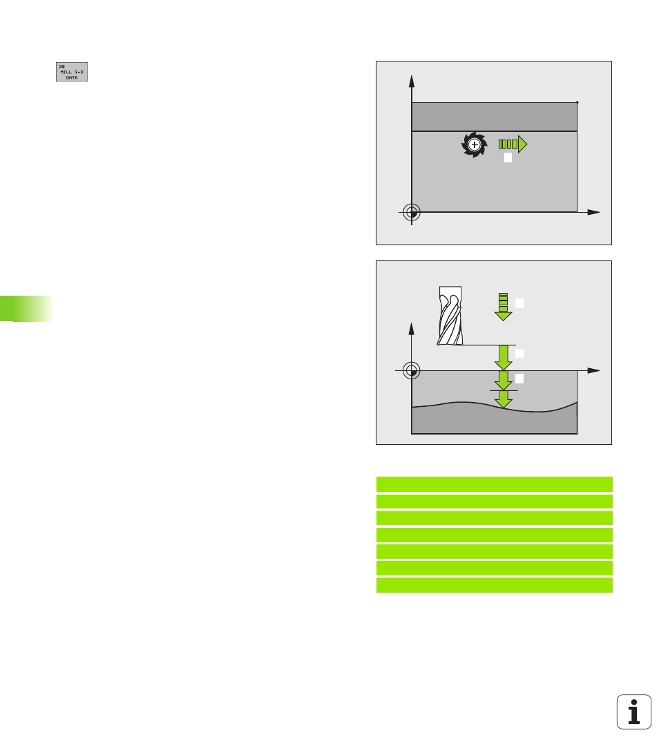
Cycle parameters
U
PGM name 3-D data
: Enter the name of the program in
which the contour data is stored. If the file is not
stored in the current directory, enter the complete
path. A maximum of 254 characters can be entered.
U
Min. point of range
: Lowest coordinates (X, Y and Z
coordinates) in the range to be milled. Input range:
-99999.9999 to 99999.9999
U
Max. point of range
: Largest coordinates (X, Y and Z
coordinates) in the range to be milled. Input range:
-99999.9999 to 99999.9999
U
Setup clearance
1
(incremental): Distance between
tool tip and workpiece surface for tool movements at
rapid traverse. Input range: 0 to 99999.9999
U
Plunging depth
2
(incremental value): Infeed per cut
Input range: -99999.9999 to 99999.9999
U
Feed rate for plunging
3
: Traversing speed of the
tool during plunging in mm/min. Input range: 0 to
99999.999; alternatively FAUTO.
U
Feed rate for plunging
4
: Traversing speed of the
tool during milling in mm/min. Input range: 0 to
99999.9999; alternatively FAUTO.
U
Miscellaneous function M
: Optional entry of one to
two miscellaneous functions, for example M13. Input
range: 0 to 999
Example: NC blocks
64 CYCL DEF 30.0 RUN 3-D DATA
65 CYCL DEF 30.1 PGM DIGIT.: BSP.H
66 CYCL DEF 30.2 X+0 Y+0 Z-20
67 CYCL DEF 30.3 X+100 Y+100 Z+0
68 CYCL DEF 30.4 SETUP 2
69 CYCL DEF 30.5 PECKG +5 F100
70 CYCL DEF 30.6 F350 M8
4
Y
X
MIN
MAX
X
Z
1
2
3