2 datum shift (cycle 7, din/iso: g54), Effect, Cycle parameters – HEIDENHAIN iTNC 530 (340 49x-05) Cycle programming User Manual
Page 262
262
Cycles: Coordinate Transformations
1
1
.2 D
A
TUM SHIFT (Cy
c
le 7
, DIN/ISO: G54)
11.2 DATUM SHIFT (Cycle 7,
DIN/ISO: G54)
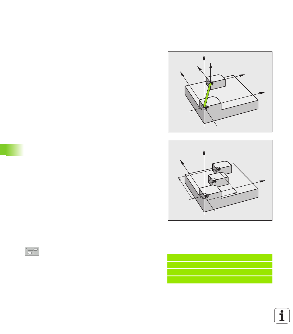
Effect
A DATUM SHIFT allows machining operations to be repeated at
various locations on the workpiece.
When the DATUM SHIFT cycle is defined, all coordinate data is based
on the new datum. The TNC displays the datum shift in each axis in
the additional status display. Input of rotary axes is also permitted.
Resetting
Program a datum shift to the coordinates X=0, Y=0 etc. directly with
a cycle definition.
Use the TRANS DATUM RESET function.
Call a datum shift to the coordinates
X=0; Y=0 etc. from the datum table.
Graphics
If you program a new BLK FORM after a datum shift, you can use
MP 7310 to determine whether the BLK FORM is referenced to the
current datum or to the original datum. Referencing a new BLK FORM
to the current datum enables you to display each part in a program in
which several pallets are machined.
Cycle parameters
U
Datum shift:
Enter the coordinates of the new
datum. Absolute values are referenced to the
manually set workpiece datum. Incremental values
are always referenced to the datum which was last
valid—this can be a datum which has already been
shifted. Input range: Up to 6 NC axes, each from
-99999.9999 to 99999.9999
Z
Z
X
X
Y
Y
Z
X
Y
X
Y
Example: NC blocks
13 CYCL DEF 7.0 DATUM SHIFT
14 CYCL DEF 7.1 X+60
16 CYCL DEF 7.3 Z-5
15 CYCL DEF 7.2 Y+40