Cycle run, Please note while programming – HEIDENHAIN iTNC 530 (340 49x-05) Cycle programming User Manual
Page 319
HEIDENHAIN iTNC 530
319
14.5 BA
SIC R
O
T
A
TION compensation via r
o
tary axis (Cy
c
le 403,
DIN/ISO:
G403)
14.5 BASIC ROTATION
compensation via rotary axis
(Cycle 403, DIN/ISO: G403)
Cycle run
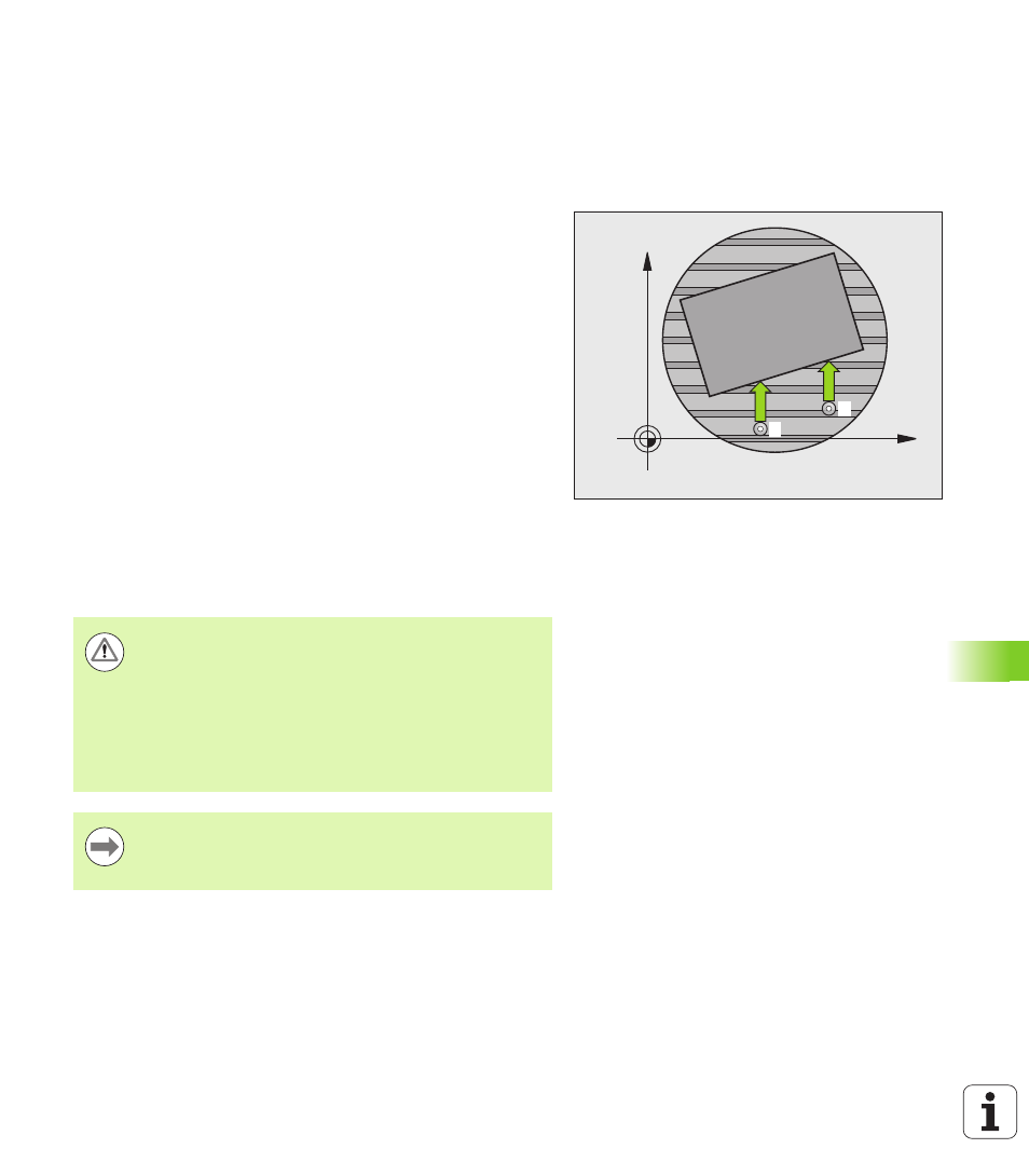
Touch Probe Cycle 403 determines a workpiece misalignment by
measuring two points, which must lie on a straight surface. The TNC
compensates the determined misalignment by rotating the A, B or C
axis. The workpiece can be clamped in any position on the rotary table.
1
Following the positioning logic (see “Executing touch probe
cycles” on page 306), the TNC positions the touch probe to the
programmed starting point
1
at rapid traverse (value from MP6150
or MP6361). The TNC offsets the touch probe by the safety
clearance in the direction opposite the defined traverse direction.
2
Then the touch probe moves to the entered measuring height and
probes the first touch point at the probing feed rate (MP6120 or
MP6360).
3
Then the touch probe moves to the next starting position
2
and
probes the second position.
4
The TNC returns the touch probe to the clearance height and
moves the rotary axis, which was defined in the cycle, by the
measured value. Optionally you can have the display set to 0 after
alignment.
Please note while programming:
X
Y
1
2
Danger of collision!
You can now also use Cycle 403 when the "Tilt the
working plane" function is active. Ensure that the
clearance height
is sufficiently large so that no collisions
can occur during the final positioning of the rotary axis.
The TNC does not check whether touch points and
compensation axis match. This can result in compensation
movements offset by 180°.
Before a cycle definition you must have programmed a
tool call to define the touch probe axis.
The TNC stores the measured angle in parameter Q150.