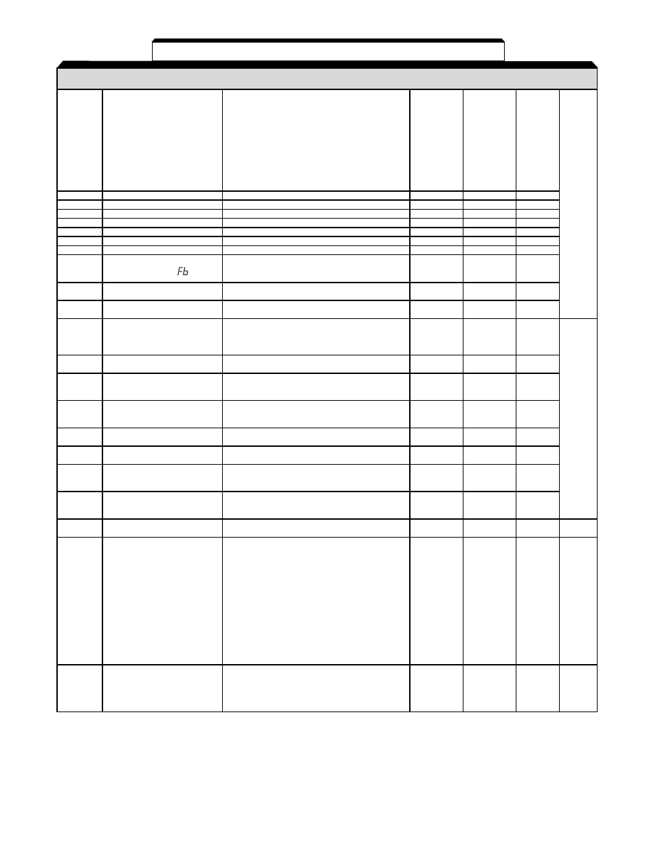
A1-6, Table a1-1. drive parameters - continued – Yaskawa V7 Drives User Manual
Page 126
A1-6
PARA-
SETTING RANGE
SETTING
FACTORY
USER
PARA.
METER
NAME
(AND UNITS)
INCREMENT
SETTING
SETTING
REF.
0:
PID control disabled
1:
D = Feed Forward
2:
D = Feedback
3:
Reference + PID (D = Feed Forward)
4:
Reference + PID (D = Feedback)
1
0
n128
PID Control Selection
5:
Inverse PID - D = Feed Forward
6:
Inverse PID - D = Feedback
7:
Inverse PID - Reference + PID
(D = Feed Forward)
8:
Inverse PID - Reference + PID
(D = Feedback)
n129
PID Feedback Gain (Note 4)
0.00 to 10.00
0.01
1.00
n130
PID Proportional Gain (Note 4)
0.00 to 25.00
0.1
1.0
n131
PID Integral Time (Note 4)
0.00 to 360.00
0.1 s
1.0
5.28
n132
PID Derivative Time (Note 4)
0.00 to 2.50
0.01
0.00
n133
PID Offset Adjustment (Note 4)
-100 to 100
1%
0
n134
Integral Value Limit (Note 4)
-100 to 100
1%
100
n135
PID Output Lag Filter Time (Note 4)
0.0 to 10.0
0.1 s
0.0
Feedback Loss
0:
Disabled
n136
1:
Enabled - Alarm (operation continues)
1
0
Detection Selection
(
)
2:
Enabled Fault (coast to stop)
n137
Feedback Loss
Detection Level
0 to 100
1%
0
n138
Feedback Loss
Detection Time
0.0 to 25.5
0.1 s
1.0
0:
Energy saving disabled
n139
Energy Saving Selection
1:
Energy saving enabled
1
0
(Note 2)
Note: Energy saving becomes enabled by
(Energy Saving)
V/f control mode
n140
Energy Saving Gain
K2 (Energy Saving)
0.00 to 6550
0.1 or 1
(Note 1)
Energy Saving Voltage
0 to 120
1%
50
n141
Lower Limit at 60 Hz
(Energy Saving)
Energy Saving Voltage
0 to 25
1%
12
n142
Lower Limit at 6 Hz
(Energy Saving)
5.31
n143
Time of Average kW
1 to 200
1
1
(Energy Saving)
(x 24 ms)
(24 ms)
n144
Voltage Limit of Tuning
1 to 100
1%
0
(Energy Saving)
n145
Step Voltage of Tuning to
100% Output Voltage
0.1 to 10.0
0.1%
0.5
(Energy Saving)
n146
Step Voltage of Tuning to
5% Output Voltage
0.1 to 10.0
0.1%
0.2
(Energy Saving)
n149
Pulse Train Input Scaling
100 to 3300
1 (x 10 Hz)
3072
5.11
(30,720 Hz)
Output Frequency Monitor:
0:
1440 Hz / Max. output frequency
1:
1f output
6:
6f output
12: 12f output
24: 24f output
0, 1, 6, 12,
n150
Pulse Monitor Output
36: 36f output
24, 36, 40,
0
5.17
Frequency Selection
Frequency Reference Monitor:
41, 42, 43,
40: 1440Hz / Max. output frequency
44, 45
41: Frequency reference * 1
42: Frequency reference * 6
43: Frequency reference * 12
44: Frequency reference * 24
45: Frequency reference * 36
0:
Fault - Coast to stop
1:
Fault - Ramp to stop (n020)
n151
Modbus Time Out
2:
Fault - Ramp to stop (n022)
1
0
5.14
Detection
3:
Alarm - operation continues
4:
Disabled
Table A1-1. Drive Parameters - Continued