Appendix 2 - specifications, Appendix 2, Appendix 2. specifications – Yaskawa V7 Drives User Manual
Page 129: A2-1, Table a2-1. standard specifications
A2-1
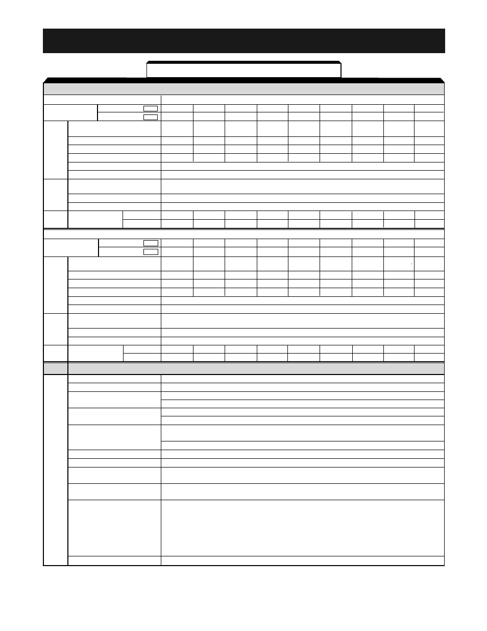
Appendix 2. SPECIFICATIONS
SECTION A. Model No. Related Specifications
230V Class
Model
CIMR-V7*
20P1
20P2
20P4
20P7
21P5
22P2
23P7
25P5
27P5
MV
A001
A002
A003
A005
A008
A011
A017
A025
A033
Max. applicable motor output
1/8
1/4
1/2
3/4&1
2
3
5
7.5
10
HP
(1)
Drive capacity (kVA)
0.3
0.6
1.1
1.9
3.0
4.2
6.7
9.5
13
Rated Output Current (A)
0.8
1.6
3.0
5.0
8.0
11.0
17.5
25
33
(5)
Rated Input Current (A)
1.1
1.8
3.9
6.4
11.0
15.1
24.0
33.0
39.6
Max. Output Voltage (V)
200 to 230V (proportional to input voltage)
Max. Output Frequency (Hz)
400 Hz (programmable)
Rated Input Voltage and
3-phase. 200 to 230 V, 50/60 Hz
Frequency
Allowable voltage fluctuation
-15% to +10%
Allowable frequency fluctuation
±5%
Cooling Method
NEMA 1
self
self
self
fan
fan
fan
fan
fan(2)
fan(2)
(QTY)
NEMA 4
self
self
self
self
fan
fan
fan
self
self
460V Class
Model
CIMR-V7*
- -
40P2
40P4
40P7
41P5
42P2
43P7
45P5
47P5
MV
- -
B001
B002
B003
B005
- -
B009
B015
- -
Max. applicable motor
output HP
(1)
- -
1/2
3/4
1&2
3
3
5
Drive capacity (kVA)
- -
0.9
1.4
2.6
3.7
4.2
7
11
16
(6)
Rated Output Current (A)
- -
1.2
1.8
3.4
4.8
5.5
8.6
14.8
21
(6)
Rated Input Current (A)
- -
1.6
2.4
4.7
7.0
8.1
12.0
19.6
27.8
(6)
Max. Output Voltage (V)
380 to 460V (proportional to input voltage)
Max. Output Frequency (Hz)
400 Hz (programmable)
Rated Input Voltage and
3-phase. 380 to 460 V, 50/60 Hz
Frequency
Allowable voltage fluctuation
-15% to +10%
Allowable frequency fluctuation
±5%
Cooling Method
NEMA 1
- -
self
self
self
fan
fan
fan
fan(2)
fan(2)
(QTY)
NEMA 4
- -
self
self
self
fan
fan
fan
self
self
SECTION B. All Drives
Control method
Sine wave PWM (V/f Control or Open Loop Vector)
Frequency control range
0.1 to 400 Hz
Frequency accuracy
Digital command: ±0.01% (14 to 122°F, -10 to +50°C)
(temperature change)
Analog command: ±0.5% (77°F ± 18°F, 25°C ± 10°C)
Open Loop Vector: ±0.2%
Speed Regulation
V/Hz Mode: ±0.5% – 1% with Slip Compensation
Digital Operator reference: 0.01 Hz (< 100Hz)
Frequency setting resolution
0.1 Hz (100Hz or more)
Analog reference: 0.06Hz/60Hz (1/1000)
Output frequency resolution
0.01 Hz
Overload capacity
150% of rated output current for 1 minute
0 to 10VDC (20k
Ω), 4 to 20mA (250Ω), 0 to 20mA (250Ω) pulse train input,
Frequency Reference Signal
Digital Operator Pot
0.01 to 6000 sec.
Accel/Decel Time
(accel/decel time are independently programmed)
Short-term average deceleration torque (2)
0.2kW: 150%
0.75kW: 100%
Braking Torque
1.5kW: 50%
2.2kW or more: 20%
Continuous regenerative torque: Approx. 20% (150% with
optional braking resistor, braking transistor built-in)
V/f characteristics
Custom V/f pattern
Table A2-1. Standard Specifications
Output
Char
acter
istics
Po
w
e
r
Supply
Output
Char
acter
istics
Control Char
acter
istics
Po
w
e
r
Supply
Ph
ysical
Char
acter-
istics
Ph
ysical
Char
acter-
istics
15
(6)
7.5 &
10
(table continued on next page)
See notes at end of table.