Chapter 4 - digital operator, 1 general, 2 digital operator – Yaskawa V7 Drives User Manual
Page 49: Digital operator -1, General -1
4-1
All functions of the Drive are accessed using the Digital Operator. In addition to controlling motor
operation, the operator can enter information into the Drive memory to configure the Drive’s applica-
tion, by using the Function LEDs.
A.
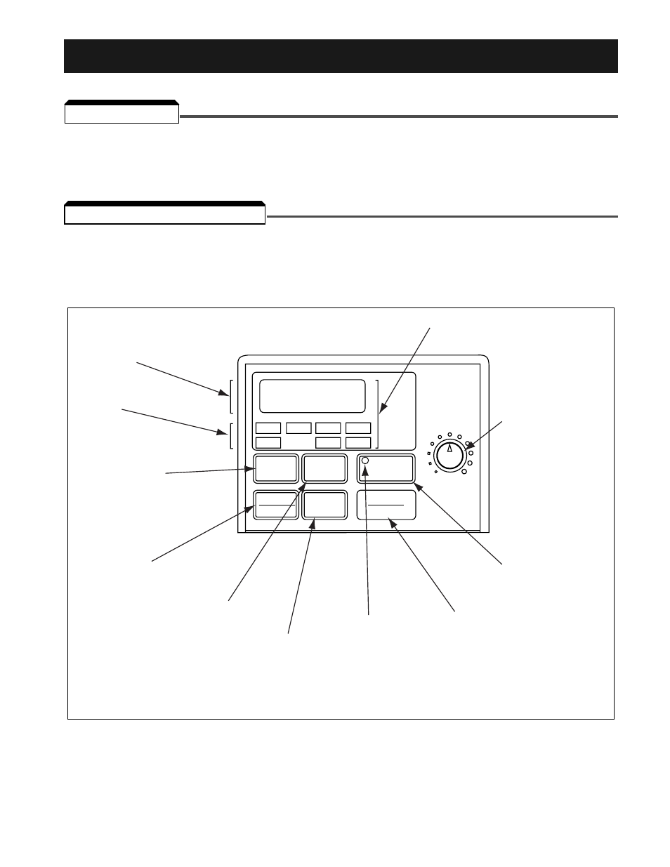
Digital Operator Description
The Digital Operator has a 4-digit LED display. Both numeric and alpha-numeric data can appear on
the display. Indicators and keys on the Digital Operator are described in Figure 4-1.
4.1 GENERAL
4.2 DIGITAL OPERATOR
Section 4. DIGITAL OPERATOR
MIN
MAX
STOP
RESET
DATA
ENTER
FREF
FOUT
IOUT
MNTR
F/R
LO/RE
PRGM
DSPL
Digital Operator
Potentiometer
(Pot)
Display section
Data display
section
Function
LEDs
Press to switch
between function
LEDs.
RUN
DIGITAL
OPERATOR
JVOP-140
Press to stop the motor,
or reset a drive fault
Status indicator
Press to decrease
parameter no./data
value.
Press to increase
parameter no./data
value.
Press to run the motor.
V
V
Displays data
to be changed
and enters new
data.
(1) Not available on V74X.
NOTE:
The JVOP-140 is the standard digital operator for the V7. The Digital Operator of the V74X does not
have a potentiometer (pot) and cannot be removed. All functions will be identical with the exception of
the pot and copy function (section 5-29).