Control circuit, 230v 3-phase input – Yaskawa V7 Drives User Manual
Page 25
Tightening
Wire
Model
Terminal Symbol
Screw
Torque
Applicable size
Recommended
lb • in (N • m)
size
Type
mm
2
AWG
mm
2
AWG
MA, MB, MC
M3
4.44 to 5.33
twisted wire 0.5 to 1.25 20 to 16
0.75
18
Common
(0.5 to 0.6)
single
0.5 to 1.25 20 to 16
Shielded
to
S1 to S7, P1, P2, SC,
1.94 to 2.21
twisted wire 0.5 to 0.75 20 to 18
wire or
all models
PC, R+, R-, S+, S-,
M2
(0.22 to 0.25) single
0.5 to 1.25 20 to 16
0.75
18
equivalent
FS, FR, FC, AM, AC, RP
Model
Tightening
Wire
Terminal Symbol
Screw
Torque
Applicable
Recommended
CIMR-
lb • in
size
size
Type
V7*
MV
(N • m)
mm
2
AWG
mm
2
AWG
20P1
A001
M3.5
7.1 to 8.88
0.75 to 2 18 to
2
14
(0.8 to 1.0)
14
20P2
A002
M3.5
7.1 to 8.88
0.75 to 2 18 to
2
14
(0.8 to 1.0)
14
20P4
A003
R/L1, S/L2, T/L3
M3.5
7.1 to 8.88
0.75 to 2 18 to
2
14
B1, B2
(0.8 to 1.0)
10
20P7
A005
U/T1, V/T2, W/T3
M3.5
7.1 to 8.88
0.75 to 2 18 to
2
14
-, +1,+2
(0.8 to 1.0)
14
600V
21P5
A008
M4
10.65 to 13.31 2 to 5.5 14 to
2
14
vinyl-
(1.2 to 1.5)
10
sheathed
22P2
A011
M4
10.65 to 13.31 2 to 5.5 14 to
3.5
12
wire or
(1.2 to 1.5)
10
equivalent
23P7
A017
M4
10.65 to 13.31 2 to 5.5 14 to
5.5
10
(1.2 to 1.5)
10
25P5
A025
M5
22.19
5.5 to 8 10 to 8
8
8
(2.5)
27P5
A033
M5
22.19
5.5 to 8 10 to 8
8
8
(2.5)
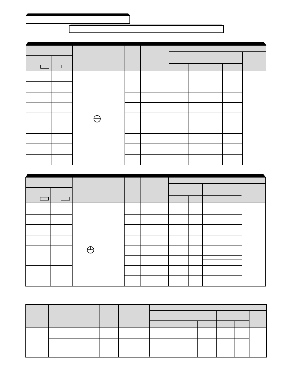
Table 1-1. Wire and Terminal Screw Sizes
Continued
1.4 ELECTRICAL INSTALLATION
230V 3-phase Input
Control Circuit
Note: The wire size is set for copper wires at 160°F (75°C)
Model
Tightening
Wire
Terminal Symbol
Screw
Torque
Applicable
Recommended
CIMR-
lb • in
size
size
Type
V7*
MV
(N • m)
mm
2
AWG
mm
2
AWG
40P2
B001
M4
10.65 to 13.31 2 to 5.5 14 to
2
14
(1.2 to 1.5)
10
40P4
B002
M4
10.65 to 13.31 2 to 5.5 14 to
2
14
(1.2 to 1.5)
10
600V
40P7
B003
R/L1, S/L2, T/L3
M4
10.65 to 13.31 2 to 5.5 14 to
2
14
vinyl-
B1, B2
(1.2 to 1.5)
10
sheathed
41P5
B005
U/T1, V/T2, W/T3
M4
10.65 to 13.31 2 to 5.5 14 to
2
14
wire or
-, +1,+2
(1.2 to 1.5)
10
equivalent
42P2
–
x 1
M4
10.65 to 13.31 2 to 5.5 14 to
2
14
(1.2 to 1.5)
10
43P7
B009
M4
10.65 to 13.31 2 to 5.5 14 to
2
14
(1.2 to 1.5)
10
3.5 x 1
12 x 1
45P5
B015
M4
12.43
3.5 to 5.5 12 to
5.5
10
(1.4)
10
47P5
—
M5
22.19
5.5 to 8
12 to
5.5
10
(2.5)
10
460V 3-phase Input
1-7