Caution, Continued 1.4 electrical installation – Yaskawa V7 Drives User Manual
Page 33
1-15
Continued
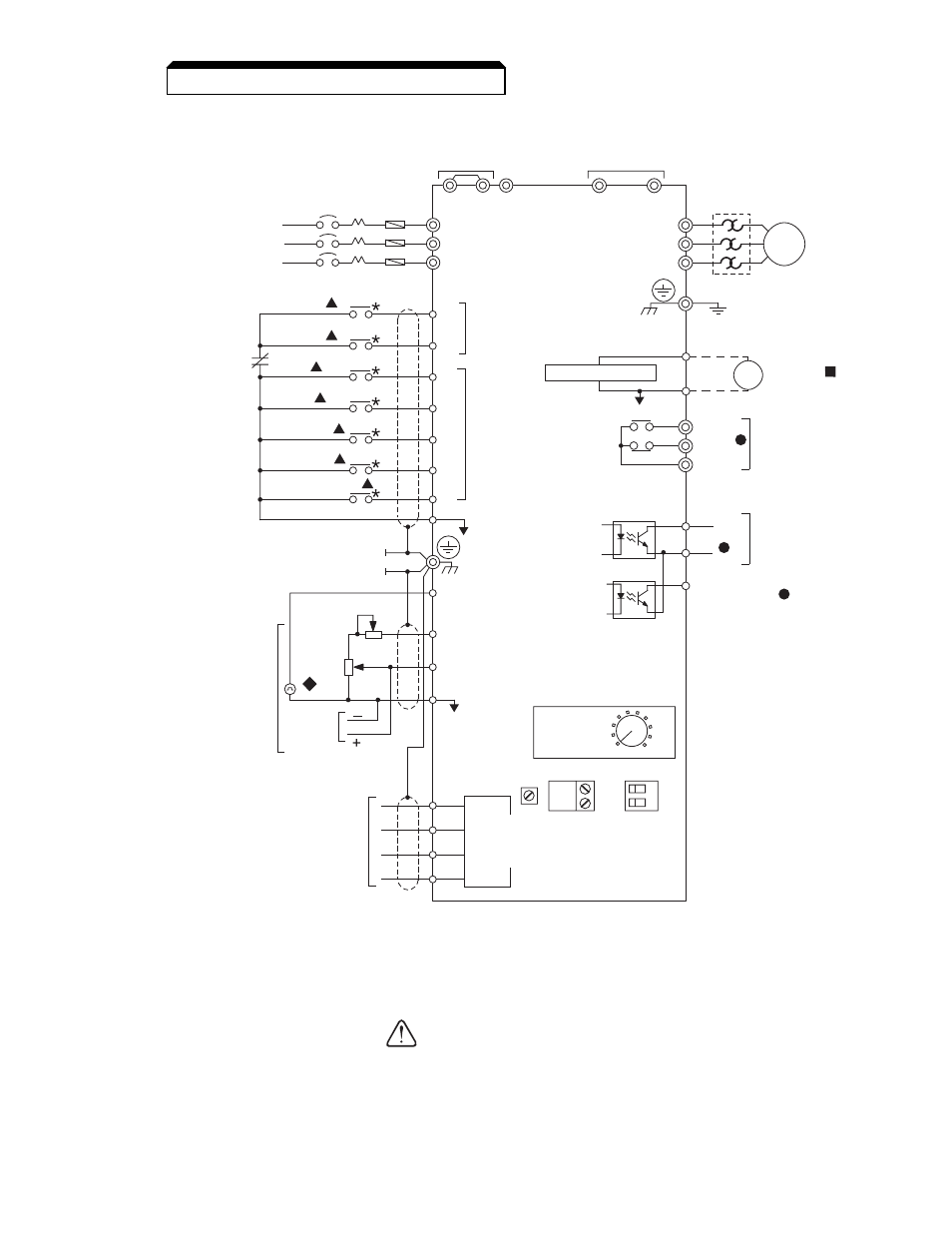
1.4 ELECTRICAL INSTALLATION
L1 ( R )
L2 ( S )
L3 ( T )
FREQUENCY
PULSE TRAIN INPUT
(MAX 30KHz)
SETTING POWER SUPPLY
(+12V, 20mA) (See Note 2)
REFERENCE
FREQUENCY
SETTING
POT
(0 to 10V, 20KΩ /
4 to 20mA, 250Ω )
MIN
SW1
SW2
PNP
NPN
OFF
V
1 ON
I
2
MAX
P1
PC
B2
B1
–
+2
+1
AC
MOTOR
T1 ( U )
T2 ( V )
T3 ( W )
MCCB
L1
L2
L3
S1
FORWARD
RUN/STOP
LOGIC
COMMON
TERMINAL
FREQUENCY
REF.
MULTI-FUNCTION
PHOTOCOUPLER
OUTPUT
48V, 50mA OR LESS
3-PHASE
POWER SUPPLY
(Use L1 (R) and
(Note that drive must
be derated by 50%
on 3-Phase Models)
L2 (S) for
single-phase
input)
MULTI-FUNCTION
OUTPUT CONTACT
250VAC, 1A OR LESS
30VDC, 1A OR LESS
SHIELD
CONNECTION
ANALOG MONITOR
REVERSE
RUN/STOP
S2
S3
S4
S5
S6
FAULT
RESET
EXTERNAL
FAULT
MULTI-STEP
SPEED REF 1
S7
SC
FC
OV
FS
RP
FR
R+
R-
S+
S-
AM
AC
FM
ANALOG OUTPUT
MONITOR 0 to +10VDC
V7
OUTPUT
FREQUENCY
MULTI-FUNCTION
CONTACT INPUT
MA
MB
MC
RUNNING
FAULT
FOR DYNAMIC BRAKING
(See Note 6)
FOR DC REACTOR
(See Note 7)
(See Note 5)
*
P2
SPEED
COINCIDENCE
*
*
(See Note 8)
(See Note 5)
MODBUS
COMMUNICATIONS
RS485/422
19.2 KBPS MAX.
(See Note 4)
(See Note 1)
1RH
MANUAL
SPEED
2KΩ
0-10VDC
or
4-20mA
1OL (See Note 3)
*
*
*
*
1OL
See
Note 3)
1R
2K
MULTI-STEP
SPEED REF 2
JOG REFERENCE
MODBUS
(TERMINAL
RESISTANCE:
120Ω, 0.5W)
FIG. 1-9
V74X
OR
1-3FU*
(See Note 9)
Figure 1-5. Standard Connections (2-Wire Control)
(Parameter n001 set to “10”)
H. Inspection. After wiring is complete, verify that all wiring is correctly installed,
excess screws and wire clippings are removed from inside of unit, screws are
securely tightened, and exposed wire does not contact other wiring or terminals.
If a FWD or REV run command is given from the con-
trol circuit terminal when the operation method selec-
tion function (
n003 ) is set to “ 1 ” and the “LO/RE”
selection is set to “RE”, the motor will start automatical-
ly as soon as power is applied to the main circuit.
CAUTION