Drive simplified startup procedure, Power wiring schematic, Simplified startup procedure – Yaskawa V7 Drives User Manual
Page 7: Caution
- v -
This procedure is a simplified step by step guide to installing, programming, and using the
Yaskawa V7 & V74X (hereafter referred to as the Drive). It highlights several common installation
configurations. Detailed information on all drive features can be found in Technical Manual.
❏ Check Nameplate - Be certain your input voltage source, motor and drive nameplates are all
marked either 230V or 460V. Other voltages can be used, but require additional programming; see
paragraph 5.27, V/f pattern.
❏ Mount drive - on a vertical surface with adequate space for air circulation (4.7" above and below,
1.2" on each side).
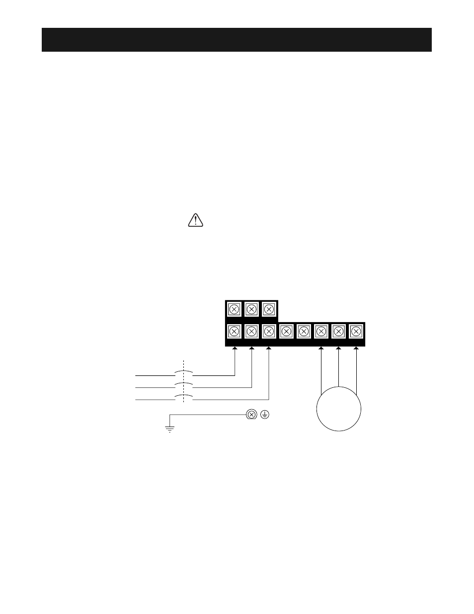
❏ Remove front cover - fit conduit to bottom plate, and connect power and ground wires as shown.
BE CERTAIN YOU CONNECT INPUT POWER TO TERMINALS L1, L2, AND L3
ONLY, OR SERIOUS DAMAGE WILL RESULT. CONNECT MOTOR TO TERMINALS
T1, T2, AND T3 ONLY.
POWER WIRING SCHEMATIC
❏ Replace cover and apply input power – digital operator shows “0.00”; The FREF LED
is on and the RUN LED is flashing. Press the DSPL key until the LO/RE LED is on.
Press the UP ARROW button until the display shows “Lo,” then press the DSPL button until the
FREF LED is on. Rotate the potentiometer on the front of the digital operator until the display
shows “6.00.” Press the RUN button and note the direction of motor rotation. If rotation is incorrect,
remove power, wait for the display lights to go out, then switch wires between terminals T1 and T2.
Replace the front cover and apply input power.
3 PHASE
INPUT
POWER
MOTOR
WIRE TO
EARTH GROUND
Note:
Exact terminal configuration
may vary with drive rating
R/L1 S/L2 T/L3
–
+1
+2
B1
B2
U/T1 V/T2 W/T3
SIMPLIFIED STARTUP PROCEDURE
CAUTION