Yaskawa iQpump Manual Supplement User Manual
Page 64
64
YASKAWA TM.iQp.10 Technical Manual Supplement
Analog Outputs
H4-01
041D
Terminal FM Monitor
Selection
Terminal FM Sel
Selects which monitor will be output on Terminals FM and AC.
1: Frequency Ref (100 % = max. output frequency)
2: Output Freq (100 % = max. output frequency)
3: Output Current (100 % = drive rated current)
6: Output Voltage (100 % = 230 V or 100 % = 460 V)
7: DC Bus Voltage (100 % = 400 V or 100 % = 800 V)
8: Output kWatts (100 % = drive rated power)
15: Term A1 Level
16: Term A2 Level
18: Mot SEC Current (100 % = Motor rated secondary current)
20: SFS Output (100 % = max. output frequency)
24: PI Feedback
31: Not Used
36: PI Input
37: PI Output (100% = max. output frequency)
38: PI Set-point
Note: 100% = 10 V DC output x FM gain setting (H4-02).
1 ~ 38
<0032>
2
Programming
H4-02
041E
Terminal FM Gain Setting
Terminal FM Gain
Sets Terminal FM output voltage (in percent of 10 V) when selected
monitor is at 100 % output.
0.0 ~
1000.0 %
100.0 %
Programming
H4-03
041F
Terminal FM Bias Setting
Terminal FM Bias
Sets Terminal FM output voltage (in percent of 10 V) when selected
monitor is at 0 % output.
–110.0 ~
+110.0 %
0.0 %
Programming
H4-04
0420
Terminal AM Monitor
Selection
Terminal AM Sel
Selects which monitor will be output on Terminals AM and AC.
1: Frequency Ref (100 % = max. output frequency)
2: Output Freq (100 % = max. output frequency)
3: Output Current (100 % = drive rated current)
6: Output Voltage (100 % = 230 V or 100 % = 460 V)
7: DC Bus Voltage (100 % = 400 V or 100% = 800 V)
8: Output kWatts (100 % = drive rated power)
15: Term A1 Level
16: Term A2 Level
18: Mot SEC Current (100 % = Motor rated secondary current)
20: SFS Output (100 % = max. output frequency)
24: PI Feedback
31: Not Used
36: PI Input
37: PI Output (100 % % = max. output frequency)
38: PI Set-point
Note: 100 % = 10 V DC output x AM gain setting (H4-05).
1 ~ 38
<0032>
8
Programming
H4-05
0421
Terminal AM Gain Setting
Terminal AM Gain
Sets Terminal AM output voltage (in percent of 10 V) when selected
monitor is at 100 % output.
0.0 ~
1000.0 %
50.0 %
Programming
H4-06
0422
Terminal AM Bias Setting
Terminal AM Bias
Sets Terminal AM output voltage (in percent of 10 V) when selected
monitor is at 0 % output.
–110.0 ~
+110.0 %
0.0 %
Programming
H4-07
0423
Terminal FM Signal Level
Selection
AO Level Select1
0: 0 - 10 Vdc
2: 4 - 20 mA*
0 or 2
0
Programming
H4-08
0424
Terminal AM Signal Level
Selection
AO Level Select2
0: 0 - 10 Vdc
2: 4 - 20 mA*
0 or 2
0
Programming
Denotes that parameter can be changed when the drive is running. * An analog output of 4 - 20 mA cannot be used with the standard terminal board. Therefore an
optional terminal board (with shunt connector CN15) is needed.
Serial Communication Setup
H5-01
0425
Drive Node Address
Serial Com Adr
Selects drive station node number (address) for Terminals R+, R-, S+, S-.
Note: An address of “0” disables serial com.
Drive power must be cycled before the changes will take effect.
*Range is dependent on P9-25, if P1-01 = 3.
<0034>
0 ~ 20*
1F
Programming
H5-02
0426
Communication Speed
Selection
Serial Baud Rate
Selects the baud rate for Terminals R+, R-, S+ and S-.
0: 1200 Baud
1: 2400 Baud
2: 4800 Baud (APOGEE FLN)
3: 9600 Baud (Metasys N2)
4: 19200 Baud
Note: Drive power must be cycled before the changes will take effect.
<0034>
0 ~ 4
3
Programming
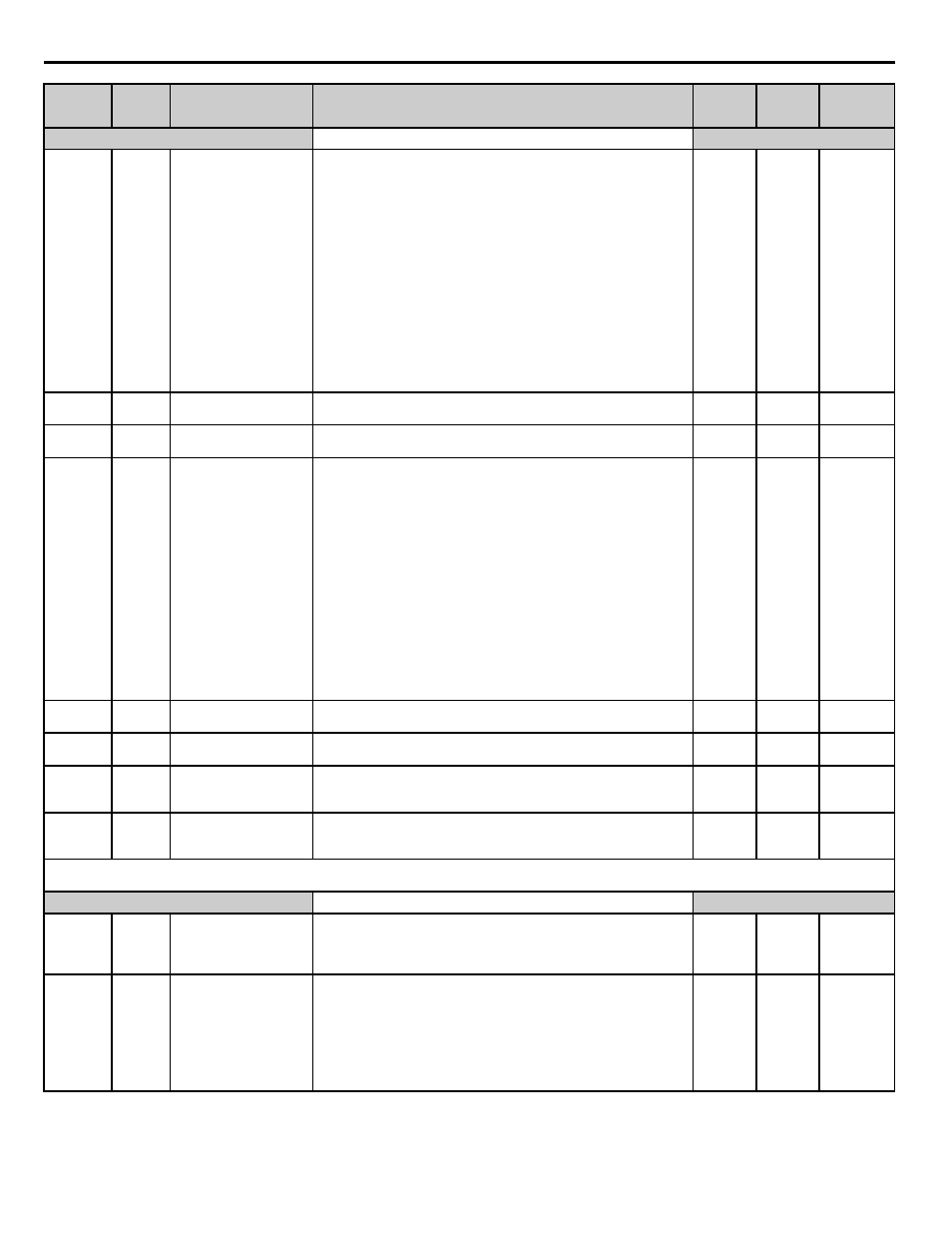
Parameter
No.
Addr.
Hex
Parameter Name
Digital Operator
Display
Description
Setting
Range
Factory
Setting
Menu
Location