Yaskawa iQpump Manual Supplement User Manual
Page 71
YASKAWA TM.iQp.10 Technical Manual Supplement
71
Pump Basic
P1-01
0600
Pump Mode
Pump Mode
Select type of control operation.
0: Drive Only (Simplex)
1: Drive + 1 Pump
2: Drive + 2 Pumps
3: Memobus network
<0034>
0 ~ 3
0
Programming
P1-02
0601
System Units
System Units
0: WC:InchOfWater
1: psi:lb/SqrInch
2: GPM:Gallons/min
3: F:DegFarenheit
4: CFM:Cubic ft/min
5: CMH:Cubic m/hr
6: LPH:Liters/hr
7: LPS:Liters/s
8: Bar:Bar
9: Pa:Pascals
10: C:DegCelsius
11: Ft: Feet
<0032>
12:%: Percent
13: rpm: Revs/min (Note 1)
<0034>
14: Hz: Hertz (Note 1)
<0034>
0 ~ 14
1
Programming
P1-03
0602
Feedback Device Scaling
Fb Dev Scaling
Scaling of feedback device in user units (P1-02=1, e.g. 150 psi).
Digits 1 through 4 set the maximum feedback number. Digit 5 determines
the number of decimal places.
Digit 5 = 0: Number format is XXXX
Digit 5 = 1: Number format is XXX.X
Digit 5 = 2: Number format is XX.XX
Digit 5 = 3: Number format is X.XXX
Examples:
01000 = 1000
13000 = 300.0
25000 = 50.00
32000 = 2.000
1 ~ 36000
(system
units
P1-02)
00145
Programming
P1-04
0603
Start Level
Start Level
Drive starts when the feedback level drops below the start level for a time
specified in P1-05. This level also specifies the wake up level when the
drive is in Sleep Mode.
If set to a negative value, the feedback level must drop by this amount
below the setpoint.
<0034>
Note: When PID operates in the reverse mode, the feedback value has to
rise above the start level for the time programmed in P1-05 for the system
to start. A value of 0 disables this function.
If P1-01 = 3, the function is active only on the first drive in the network.
<0034>
- 999.9 ~
999.9
(system
units
P1-02)
0.0 (system
units
P1-02)
Pump Quick
Setup
P1-05
0604
Start Level Delay Time
S-Lvl Delay Time
Drive starts when the feedback level drops below the start level for a time
specified in P1-05.
0 ~ 3600
sec
1 sec
Programming
P1-06
0605
Minimum Pump
Frequency
Min. Pump Freq
Minimum drive frequency when operated in the auto mode. Programmed
value will limit minimum PID output. Minimum value must be
programmed to a value smaller than P3-09 and P3-10 when drive is
operating in the multiplex mode (P1-01).
0.0 ~
120.0 Hz
40.0 Hz
Pump Quick
Setup
P1-07
0606
Low Feedback Level
Low FB Level
The drive will display a “Low Feedback (LFB)” alarm when the feedback
level falls below the programmed level. The alarm will turn off when the
feedback level rises above the programmed Low Feedback Level plus the
Hysteresis Level (P1-13). A value of 0 disables this function. This function
is only active during running while operating in the auto mode.
0.0 ~
6000.0
(system
units
P1-02)
0.0 (system
units
P1-02)
Programming
P1-08
0607
Low Feedback Level Fault
Delay Time
Low Lvl Flt Time
The drive will display a “Low Feedback/Water (LFB/LW)” alarm when the
feedback level falls below the programmed level for a time specified in P1-
08. The drive will coast to a stop when a fault occurs. A value of 0 disables
this function. This function is only active during running while operating
in the auto mode.
If P1-01 = 3, the function will stop all drives running on the network when
the system fault occurs.
<0034>
0 ~ 3600
sec
5 sec
Programming
Denotes that parameter can be changed when the drive is running.
Note 1: When P1-02 = 3, parameter P1-03 must be set to (120 x E1-04/E2-04) for proper display. When P1-02 = 14, parameter P1-03 must be set to the same value as E1-
04 for proper display.
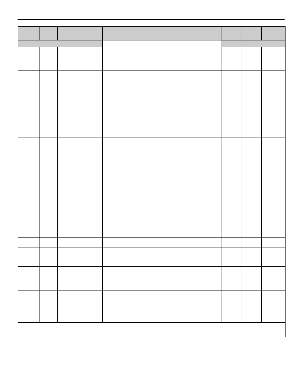
Parameter
No.
Addr.
Hex
Parameter Name
Digital Operator
Display
Description
Setting
Range
Factory
Setting
Menu
Location