Yaskawa iQpump Manual Supplement User Manual
Page 79
YASKAWA TM.iQp.10 Technical Manual Supplement
79
P4-21
<0034>
834
Low City Pressure Input
Select
Low City In Sel
Selects the type of pressure switch connected to the “Low City Pressure”
digital input (H1-0x = 73).
0: Normally Open (closed indicates the “Low City Pressure”
condition)
1: Normally Closed (open indicates the “Low City Pressure”
condition)
0 ~ 1
1
Programming
P4-22
<0034>
835
Low City Pressure Input
Delay
Low City Delay
Sets the amount of time a “Low City Pressure” condition must be present
before the drives will stop. Also sets the amount of time that the pressure
must be adequate before the drive system will re-start.
1 ~ 1000
sec
10 sec
Programming
P4-23
<0034>
836
Lube Pump Delay Timer
Lube Pump Time
Sets the amount of time the drive’s output will be delayed and the Lube
Pump digital output (H2-0x = 55) will be energized.
A setting of zero will disable this feature.
0.0 ~
300.0 sec
0.0 sec
Programming
P4-24
<0035>
837
Remote Drive Disable
Selection
Rem Drv Dis Sel
Selects the type of pressure switch connected to the “Remote Drv Disbl”
digital input (H1-0=72).
0: Normally Open (closed indicates the “Remote Drive Disable”
condition).
1: Normally Closed (open indicates the “Remote Drive Disable”
condition).
0.0 ~ 1
0.0 sec
Programming
P4-25
<0035>
838
Remote Drive Disable
On-Delay
Drv Dis On-Delay
Sets the amount of time a “Remote Drive Disable” condition must be
present before the drive will stop.
0 ~ 1000
sec
0 sec
Programming
P4-26
<0035>
839
Remote Drive Disable
Off-Delay
Drv Dis Off-Delay
Sets the amount of time a “Remote Drive Disable” condition must be
absent before the drive will be allowed to run.
0 ~ 1000
sec
0 sec
Programming
P4-27
<0035>
83
Low City Alarm Text
Low Cty Alrm Txt
Selects the alarm message that will be displayed when a Low City
condition is detected.
0: Low City Pressure
1: Low Suction Pressure
2: Low Water in Tank
0 ~ 2
0 sec
Programming
Parameter functionality stated below only applies when b1-01 = 5 (Geothermal Mode)
P4-31
<0035>
83B
Minimum Geothermal
Temperature Inpu
MinGeothrm Scale
Sets the temperature that corresponds to a 0V (or 4 mA) analog input.
-110.0 ~
440.0 °F
0.0
Programming
P4-32
<0035>
83C
Maximum Geothermal
Temperature Inpu
MaxGeothrm Scale
Sets the temperature that corresponds to a 10V (or 20 mA) analog input.
-110.0 ~
450.0 °F
150.0
Programming
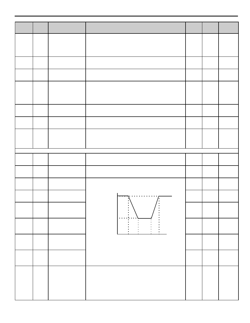
P4-33
<0035>
83D
Minimum Geothermal
Speed
MinGeothrm Speed
Sets the frequency reference characteristics based on the set temperature
points and the corresponding frequency.
For proper operation, P4-34>P4-33 and P4-38>P4-37>P4-36>P4-35.
See Function Description for more information.
0.00 ~
120.00Hz
40.00 Hz Programming
P4-34
<0035>
83E
Maximum Geothermal
Speed
MaxGeothrm Speed
0.00 ~
120.00Hz
60.00 Hz Programming
P4-35
<0035>
83F
Low Temperature to
Run at Maximum
Geothermal Speed
Low Temp @ Max
-110.0 ~
450.0 °F
55.0
Programming
P4-36
<0035>
85B
Low Temperature to
Run at Minimum
Geothermal Speed
Low Temp @ Min
-110.0 ~
450.0 °F
65.0
Programming
P4-37
<0035>
85C
Low Temperature to
Run at Minimum
Geothermal Speed
Low Temp @ Min
-110.0 ~
450.0 °F
75.0
Programming
P4-38
<0035>
85D
High Temperature to
Run at Maximum
Geothermal Speed
High Temp @ Max
-110.0 ~
450.0 °F
85.0
Programming
P4-39
<0035>
85E
Geothermal Temperature
Loss Detection
Geotherm Loss Det
Selects the drive action when the signal from Terminal A2 has gone below
3 mA or above 21 mA. Only effective when H3-08 = 2
(4-20 mA) and H3-09 = 20 (Geothermal Temp).
0: Disabled
1: Alarm
2: Fault
0 ~ 2
1
Programming
Parameter
No.
Addr.
Hex
Parameter Name
Digital Operator
Display
Description
Setting
Range
Factory
Setting
Menu
Location
Frequency Reference (Hz)
Temperature (
°
F)
P4-35
P4-34
P4-33
P4-36
P4-36 P4-38