Yaskawa iQpump Manual Supplement User Manual
Page 88
88
YASKAWA TM.iQp.10 Technical Manual Supplement
U1-16
004F
Terminal A2 Input Voltage
Term A2 level
Displays the input current (or voltage) on Terminal A2, as a percentage of 20 mA (or 10 Vdc).
U1-18
0051
Motor Secondary Current (Iq)
Mot SEC Current
Displays the amount of current being used by the motor to produce torque (Iq).
U1-20
0053
Output Frequency After Soft
Start
SFS Output
Displays the frequency reference (speed command) after the accel and decel ramps.
U1-24
0057
PI Feedback Value
PI Feedback
Displays the feedback signal when PI control is used.
U1-28
005B
CPU Number
CPU ID
Displays control board hardware revision.
U1-29
005C
kWh
kWh Lo 4 Digits
Displays the accumulated kWh.
U1-30
005D
MWh
kWh Hi 5 Digits
Displays the accumulated MWh.
U1-34
0061
First Parameter Causing an OPE
OPE Detected
Displays the parameter number causing an “OPE” fault.
U1-36
0063
PI Input
PI Input
Displays the “error” in the PI regulator. (U1-36 = PI Set-point - PI Feedback).
U1-37
0064
PI Output
PI Output
Displays the output of the PI as a percentage of maximum frequency (E1-04).
U1-38
0065
PI Set-point
PI Set-point
Displays the setpoint of the PI regulator (U1-38 = PI reference + PI bias).
U1-39
0066
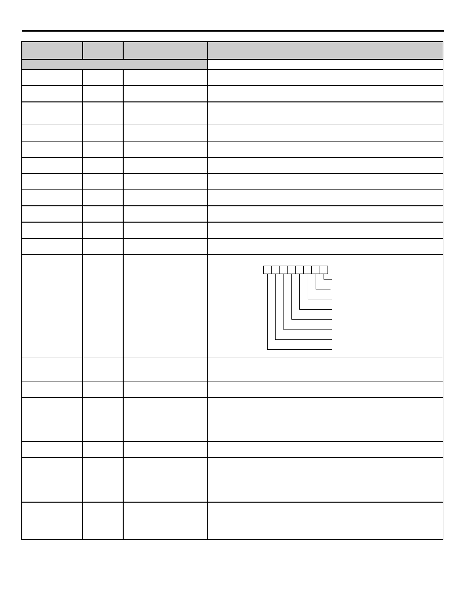
Memobus Communication Error
Code
Transmit Err
U1-40
0067
Heatsink Cooling Fan Operation
Time
FAN Elapsed Time
Displays total operating time of the heatsink cooling fan.
U1-62
007D
Running Queue No
Running Queue No
Position in the iQpump Memobus Multiplex Running Queue
U1-67
009B
Network Activity
Network Activity
Shows network traffic. A fluctuating number from 0 to 1000 denotes activity, while a
relatively constant 0 denotes no activity.
Unit changes based on network status:
<->: Drive can not communicate to other drives
<+>: Drive is a Node on a network
<M>: Drive is a Master on an iQpump Network
U1-68
0009C
Time to Alternate
Time to Alternate
Time remaining before a drive requests alternation which is dependent on P9-04.
U1-80
<0035>
009Dh
Geothermal Temperature Input
Geothermal Temp
Geothermal temperature input after the gain and bias has been applied. This is the temperature
used by the Geothermal Function to determine what frequency to run the drive.
Internally limited to -999.9°F and 999.9°F.
Only shown when B1-05 = 5
Units 0.1°F
U1-90
0720
Pump Set-point
Pump Set-point
Displays drive setpoint.
Resolution 0.1
Note: Does not include setpoint compensation (U1-93).
Parameter No.
Addr.
Hex
Parameter Name Digital
Operator Display
Description
Monitor
1: CRC error
1: Data length error
Not used. Always 0.
1: Parity error
1: Overrun error
1: Framing error
1: Timeover
Not used. Always 0
.
0 0 0 0 0 0 0 0