3 converter part names – Yaskawa Sigma-5 Large Capacity Users Manual: Design and Maintenance-Rotary Motors-Mechatrolink-II Communication Reference User Manual
Page 26
1 Outline
1-4
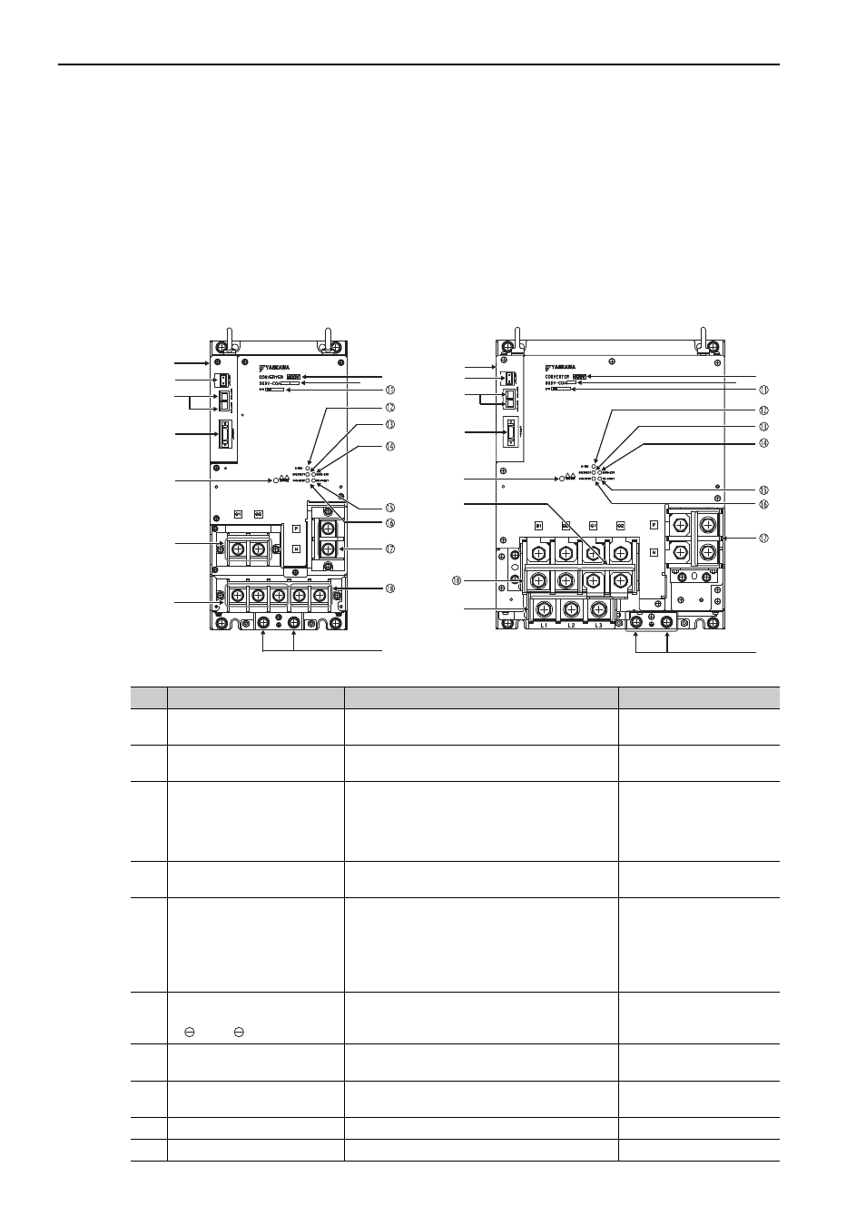
1.3 Converter Part Names
This section describes the parts of a converter.
Use a converter together with a SERVOPACK. For details, refer to 1.9 Combinations of Servomotors, SER-
VOPACKs, and Converters.
Note: For the purpose of this description, the SERVOPACK is shown with the front cover removed. Always keep the front
cover attached when using the SERVOPACK.
No.
Name
Description
Reference
Nameplate
Indicates the converter model and ratings. Located
on the side of the converter.
–
Control power input
connector (CN101)
Used to connect the control power input.
3.1 Main Circuit Wiring
Control power output
connectors
(CN103 and CN104)
These connectors output 24 VDC to the SERVO-
PACK. For a 400-V system, the 24-VDC (±15%)
input is output unaltered from CN103. CN103 and
CN104 are equivalent outputs. It is normally not
necessary to connect CN104.
–
SERVOPACK-converter I/O
connector (CN901)
Connect this connector to CN901 on the converter. –
Charge indicator
Lights (orange) when the main circuit power sup-
ply is ON and stays lit as long as the internal
capacitor remains charged. Therefore, do not touch
the SERVOPACK even after the power supply is
turned OFF if the indicator is lit. It may result in
electric shock.
–
DC reactor terminals for
harmonic suppression
( 1 and 2)
Connects a DC reactor for harmonic suppression.
3.10.3 Connecting a Reac-
tor for Harmonic Suppres-
sion
Main circuit power supply
terminals (L1, L2, and L3)
Used for main circuit power supply input.
3.1 Main Circuit Wiring
Ground terminals
Be sure to connect to protect against electrical
shock.
3.1 Main Circuit Wiring
Input voltage
–
–
Converter model
Indicates the model number of the converter.
–
SGDV-COA2BAA
SGDV-COA3ZDA
SGDV-COA3GAA
SGDV-COA5EDA
Converter
Converter