Yaskawa Sigma-5 Large Capacity Users Manual: Design and Maintenance-Rotary Motors-Mechatrolink-II Communication Reference User Manual
Page 339
9 Troubleshooting
9-28
9.4 Troubleshooting Malfunction Based on Operation and
Conditions of the Servomotor
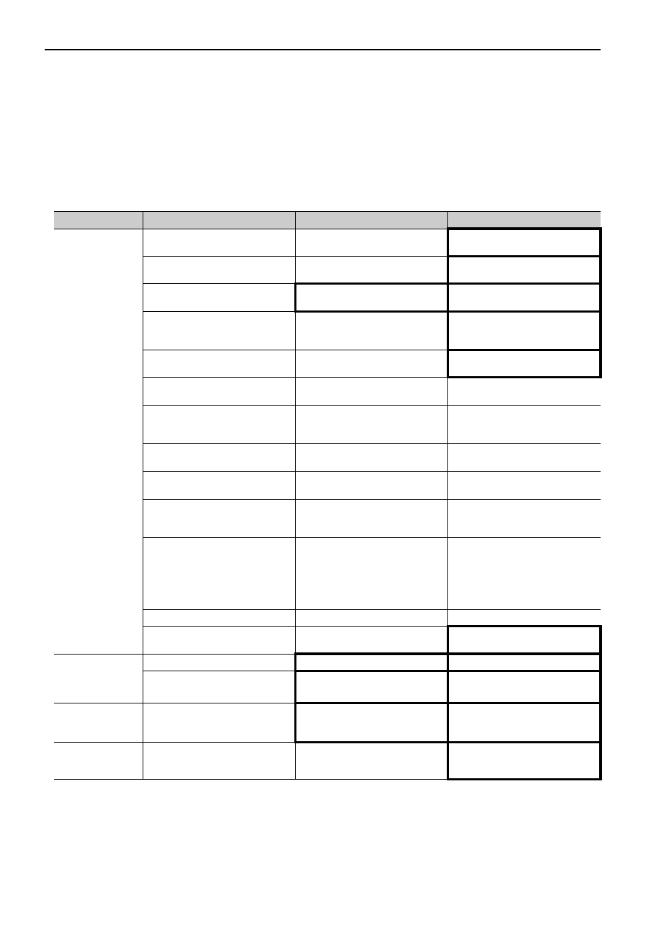
Troubleshooting for the malfunctions based on the operation and conditions of the servomotor is provided in
this section.
Be sure to turn OFF the servo system before troubleshooting items shown in bold lines in the table.
Problem
Probable Cause
Investigative Actions
Corrective Actions
Servomotor Does
Not Start
The control power supply is not
ON.
Check voltage between control
power terminals.
Correct the wiring so that the con-
trol power supply turns ON.
The main circuit power supply is
not ON.
Check the voltage between main
circuit power terminals.
Correct the wiring so that the main
circuit power supply turns ON.
Wiring of I/O signal connector CN1
is faulty or disconnected.
Check if the connector CN1 is prop-
erly inserted and connected.
Correct the connector CN1 connec-
tion.
Wiring for servomotor main circuit
cable or encoder cable is discon-
nected.
Check the wiring.
Correct the wiring.
Overloaded
Run under no load and check the
load status.
Reduce load or replace with larger
capacity servomotor.
Encoder type differs from parame-
ter setting (Pn002.2).
Check the settings for parameter
Pn002.2.
Set parameter Pn002.2 to the
encoder type being used.
Settings for the input signal selec-
tions (Pn50A, Pn50B and Pn511) is
incorrect.
Check the settings for parameters
Pn50A, Pn50B and Pn511.
Correct the settings for parameter
Pn50A, Pn50B and Pn511.
SV_ON command is not sent.
Check the command sent from the
host controller.
Send the SV_ON command.
SENS_ON command is not sent.
Check the command sent from the
host controller.
Send the command in the correct
SERVOPACK sequence.
The forward run prohibited (P-OT)
and reverse run prohibited (N-OT)
input signals are turned OFF.
Check P-OT or N-OT input signal.
Turn P-OT or N-OT input signal
ON.
The safety input signal (/HWBB1 or
/HWBB2) remains OFF.
Check the /HWBB1 and /HWBB2
input signal.
Set the /HWBB1 and /HWBB2
input signal to ON.
When not using the safety function,
mount the safety function jumper
connector (provided as an acces-
sory) on the CN8.
The brake is not released.
Check the operation of the brake.
Release the brake.
A fault occurred in the SERVO-
PACK or converter.
−
Replace the SERVOPACK or con-
verter.
Servomotor
Moves
Instantaneously,
and then Stops
Servomotor wiring is incorrect.
Check the wiring.
Correct the wiring.
Encoder wiring is incorrect.
Check the wiring.
Correct the wiring.
Servomotor
Speed Unstable
Wiring connection to servomotor is
defective.
Check connections of power line
(phases U, V, and W) and encoder
connectors.
Tighten any loose terminals or con-
nectors and correct the wiring.
Servomotor
Rotates Without
Reference Input
A fault occurred in the SERVO-
PACK.
−
Replace the SERVOPACK.