32 (3) safety output circuit – Yaskawa Sigma-5 Large Capacity Users Manual: Design and Maintenance-Rotary Motors-Mechatrolink-II Communication Reference User Manual
Page 78
3 Wiring and Connection
3.5.2 Sequence Output Circuit
3-32
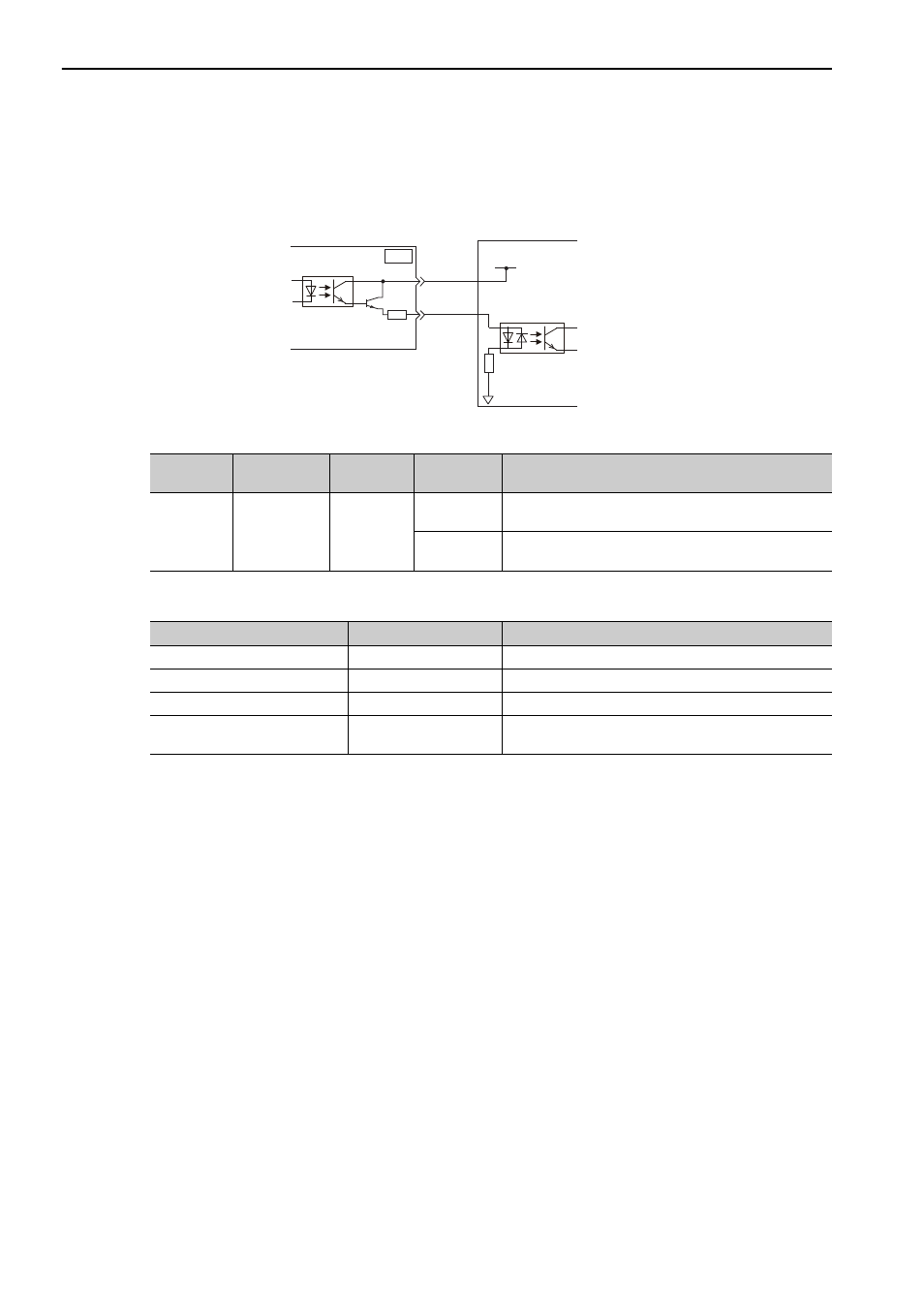
(3) Safety Output Circuit
The external device monitor (EDM1) for safety output signals is explained below.
A configuration example for the EDM1 output signal is shown in the following diagram.
Specifications
Electrical characteristics of EDM1 signal are as follows.
EDM1+
EDM1-
0 V
8
7
CN8
24 V Power Supply
SERVOPACK
Host controller
Type
Signal Name
Pin No.
Output
Status
Meaning
Output
EDM1
CN8-8
CN8-7
ON
Both the /HWBB1 and /HWBB2 signals are working nor-
mally.
OFF
The /HWBB1 signal, the /HWBB2 signal, or both are not
working normally.
Items
Characteristic
Remarks
Maximum Allowable Voltage
30 VDC
−
Maximum Current
50 mADC
−
Maximum Voltage Drop at ON
1.0 V
Voltage between EDM1+ to EDM1- at current is 50 mA.
Maximum Delay Time
20 ms
Time from the change in /HWBB1 or /HWBB2 until the
change in EDM1.