1) power supply capacities and power losses – Yaskawa Sigma-5 Large Capacity Users Manual: Design and Maintenance-Rotary Motors-Mechatrolink-II Communication Reference User Manual
Page 65
3.1 Main Circuit Wiring
3-19
3
Wi
ring and
C
onne
ctio
n
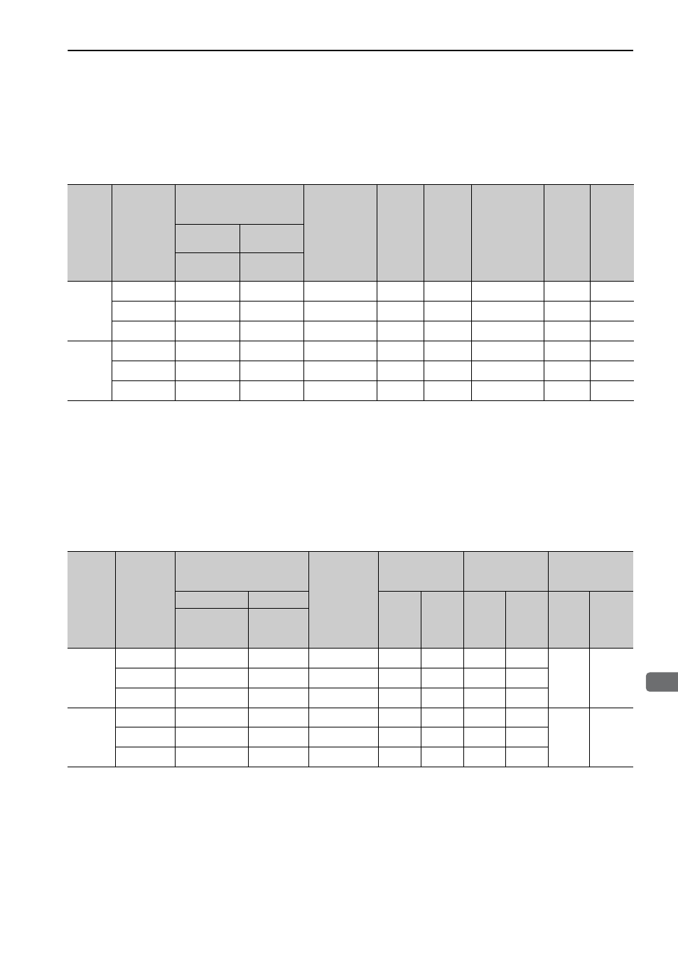
(1) Power Supply Capacities and Power Losses
The following table shows the power supply capacities and power losses of the SERVOPACKs and convert-
ers.
The values in the following table are for one combination of a SERVOPACK and converter. If there is more
than one combination of a SERVOPACK and converter, find the total for the combinations that are used.
∗1. This is the value for the JUSP-RA08-E regenerative resistor unit.
∗2. This is the value for the JUSP-RA09-E regenerative resistor unit.
∗3. This is the value for the JUSP-RA11-E regenerative resistor unit.
∗4. This is the value for the JUSP-RA13-E regenerative resistor unit.
∗5. This is the value for the JUSP-RA14-E regenerative resistor unit.
∗6. This is the value for the JUSP-RA16-E regenerative resistor unit.
(2) How to Select Molded-case Circuit Breaker and Fuse Capacities
The following table shows the current capacities and inrush current of the SERVOPACKs and converters.
Use these values as a basis for selecting the molded-case circuit breaker and fuse. If there is more than one
combination of a SERVOPACK and converter, find the total for the combinations that are used.
∗1. Input voltage of 200 VAC
∗2. Input voltage of 24 VDC
Note 1. The rated input current of the SERVOPACK is the nominal value at the rated load.
Select the appropriate capacity in accordance with the specified derating.
Cutoff characteristics (25
°C): 300% five seconds min.
2. To comply with the low voltage directive, connect a fuse to the input side. Select the fuse or molded-case circuit
breaker for the input side from among models that are compliant with UL standards.
The table above also provides the nominal values of current capacity and inrush current. Select a fuse and a
molded-case circuit breaker which meet the cutoff characteristics shown below.
• Main circuit, control circuit: No breaking at three-times the current values of the table for 5 s.
• Inrush current: No breaking at the same current values of the table for 20 ms.
Main
Circuit
Power
Supply
Maximum
Applicable
Servomotor
Capacity
[kW]
Combination of
SERVOPACK and
Converter
Power Supply
Capacity per
Combination
[kVA]
Output
Current
[Arms]
Main
Circuit
Power
Loss
[W]
Regenerative
Resistor
Power Loss
[W]
Control
Circuit
Power
Loss
[W]
Total
Power
Loss
[W]
SERVO-
PACK
Converter
Model:
SGDV-
Model:
SGDV-COA
Three-
phase
200 V
22
121H
2BAA
38
116
1200
(480)
*1
120
1320
30
161H
3GAA
52
160
1540
(960)
*2
120
1660
37
201H
3GAA
64
200
1540
(960)
*3
120
1660
Three-
phase
400 V
30
750J
3ZDA
52
76
1020
(720)
*4
96
1116
37
101J
5EDA
64
98
1240
(960)
*5
96
1336
55
131J
5EDA
95
130
1590
(1440)
*6
96
1686
Main
Circuit
Power
Supply
Maximum
Applicable
Servomo-
tor Capac-
ity
[kW]
Combination of
SERVOPACK and
Converter
Power
Supply
Capacity per
Combination
[kVA]
Current Capacity
Inrush Current
Rated voltage
SERVOPACK
Converter
Main
Circuit
[Arms]
Control
Circuit
[Arms]
Main
Circuit
[A0-p]
Control
Circuit
[A0-p]
Fuse
[V]
Circuit
Breaker
[V]
Model: SGDV-
Model:
SGDV-
COA
Three-
phase
200 V
22
121H
2BAA
38
127
1.2
*1
163
16
250
240
30
161H
3GAA
52
174
1.2
*1
163
16
37
201H
3GAA
64
214
1.2
*1
163
16
Three-
phase
400 V
30
750J
3ZDA
52
87
4
*2
170 –
600
480
37
101J
5EDA
64
107
4
*2
170 –
55
131J
5EDA
95
159
4
*2
170 –