5 servopack and converter internal block diagrams, 1 three-phase 200 v, M-ii – Yaskawa Sigma-5 Large Capacity Users Manual: Design and Maintenance-Rotary Motors-Mechatrolink-II Communication Reference User Manual
Page 32
1 Outline
1.5.1 Three-phase 200 V
1-10
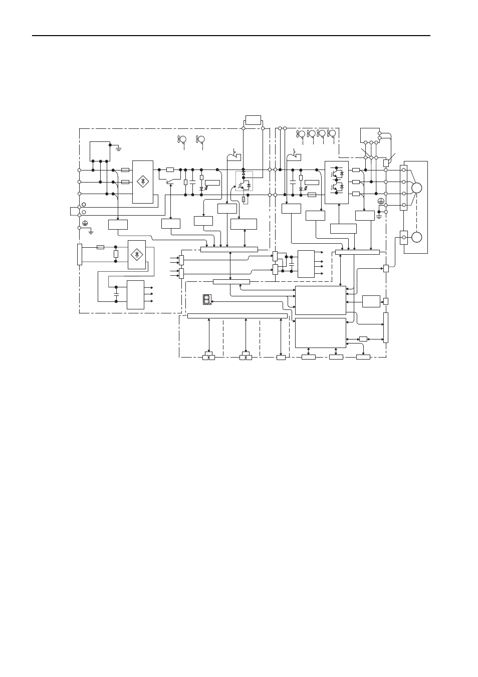
1.5 SERVOPACK and Converter Internal Block Diagrams
1.5.1 Three-phase 200 V
L1
+
B2
L2
U
V
W
- 1
L3
- 2
CHARGE
P24 V
SPD
P
N
+24 V
24C
+24 V
24C
CN103
CN104
CN901
P
N
CHARGE
ENC
M
㧗
㧙
CN103
CN104
P24 V
0 V
CN901
+24 V
6
24 V
+5 V
15 V
CN2
CN6A
CN6B
CN21
CN22
CN31
P24 V P24 V P24 V
-
B1
㧗
㧙
DU
DV
DW
CN115
CN5
CN3
CN7
CN8
CN1
I/O
㧗
㧙
㧗
㧙
Varistor
L1C
L2C
㧗
㧙
+5 V
+15 V
+24 V
2
24 V
24 V
Fan
1
Fan
2
Main circuit
power supply
Control power supply
Voltage
sensor
Control
power
supply
MC drive
Voltage sensor
gate drive
Voltage
sensor
Temperature
sensor
Converter I/O
SERVOPACK
control power supply
Panel display
Feedback option
Safety option
MECHATROLINK
communications
(M-
II
)
Fan 3
(for 55-kW
models only)
Fan
2
Fan
1
Fan
4
Voltage
sensor
Gate drive
Temperature
sensor
Current
sensor
Control
power
supply
ASIC
(PWM control, etc.)
CPU
(Position and speed
calculation, etc.)
Analog
voltage
converter
PC
Digital
operator
Safety function
signals
I/O signals
Analog monitor output
Encoder pulse output
Regenerative
resistor unit
Dynamic
brake
unit
Servomotor
M-II