3 example of i/o signal connections, Mecha – Yaskawa Sigma-5 Large Capacity Users Manual: Design and Maintenance-Rotary Motors-Mechatrolink-II Communication Reference User Manual
Page 71
3.3 I/O Signal Connections
3-25
3
Wi
ring and
C
onne
ctio
n
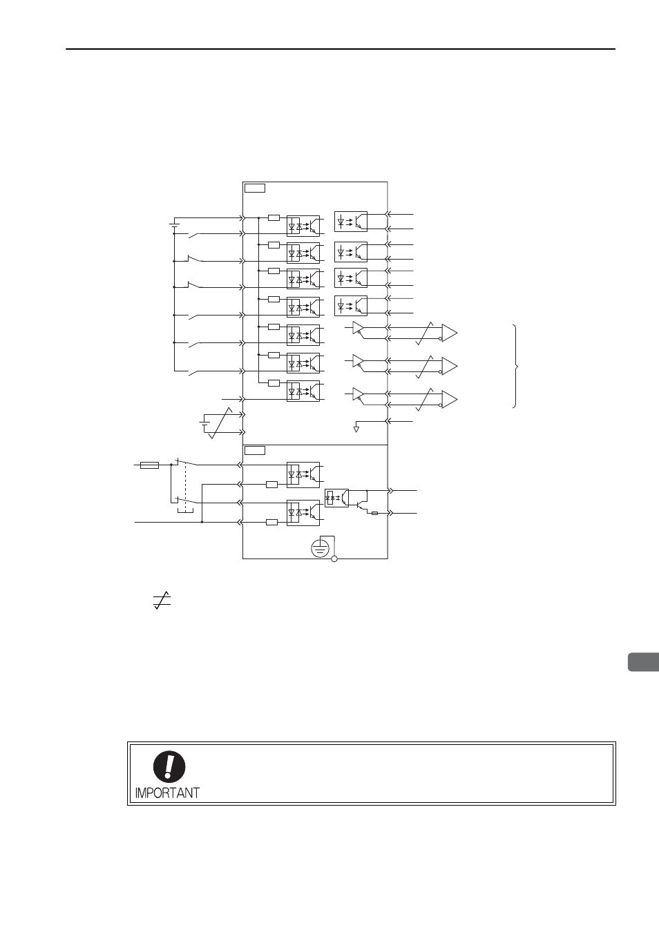
3.3.3 Example of I/O Signal Connections
The following diagram shows a typical connection example.
∗1.
represents twisted-pair wires.
∗2. Connect when using an absolute encoder. When the encoder cable with the battery case is connected, do not connect
a backup battery.
∗3. The 24-VDC power supply is not included. Use a 24-VDC power supply with double insulation or reinforced insula-
tion.
∗4. When using the safety function, a safety function device must be connected and the wiring that is necessary to acti-
vate the safety function must be done to turn ON the servomotor power. When not using the safety function, use the
SERVOPACK with the Plug (provided as an accessory) inserted into the CN8.
∗5. Always use line receivers to receive the output signals.
Note: The functions allocated to the input signals /DEC, P-OT, N-OT, /EXT1, /EXT2, and /EXT3 and the output signals
/SO1, /SO2, and /SO3 can be changed by using the parameters. Refer to 3.4.1 Input Signal Allocations and 3.4.2
Output Signal Allocations.
The number of pins on the CN1 connector is different on a large-capacity
Σ-V SERVO-
PACK (50 pins) and a standard
Σ-V SERVOPACK (26 pins). If you are using both types
of SERVOPACK, use the correct connector model numbers when ordering and the cor-
rect signal assignments.
SO1+ / BK+
SO1- / BK-
/SO2+
/SO2-
/SO3+
ALM+
ALM-
25
26
27
28
31
32
+24VIN
+24 V
3.3 k
Ω
47
42
44
43
45
46
/SI0
/DEC
P-OT
N-OT
/EXT1
/EXT2
/EXT3
General-purpose
BAT+
BAT-
40
21
22
41
/SO3-
Homing deceleration switch
(Decelerated when ON)
Control power for
sequence signals
External latch signal 1
(Latched when ON)
Reverse run prohibited
(Prohibited when OFF)
External latch signal 2
(Latched when ON)
External latch signal 3
(Latched when ON)
Backup battery
(2.8 to 4.5 V)
Forward run prohibited
(Prohibited when OFF)
Brake
(Brake released when open)
Servo alarm output
(OFF for an alarm)
Photocoupler output
Max. operating voltage: 30 VDC
Max. output current: 50 mA DC
SERVOPACK
29
30
1
SG
∗1.
∗2.
∗3.
PBO
PCO
/PBO
PAO
/PAO
/PCO
19
33
34
35
36
20
Encoder output
pulse phase A
Encoder output
pulse phase B
Encoder output
pulse phase C
Applicable line receiver:
SN75ALS175 or MC3486
manufactured by Texas
Instruments or the equivalent
EDM1+
EDM1-
FG Connect shield to
connector shell.
Connector
shell
SERVOPACK
/HWBB1+
/HWBB1-
/HWBB2+
/HWBB2-
Switch
Fuse
24 V
0 V
Safety function device*4
CN8
6
3
4
5
CN1
8
7
∗5
∗5
∗5
MECHA