Yaskawa Sigma-5 Large Capacity Users Manual: Design and Maintenance-Rotary Motors-Mechatrolink-II Communication Reference User Manual
Page 375
10 Appendix
10.1.2 Parameters
10-30
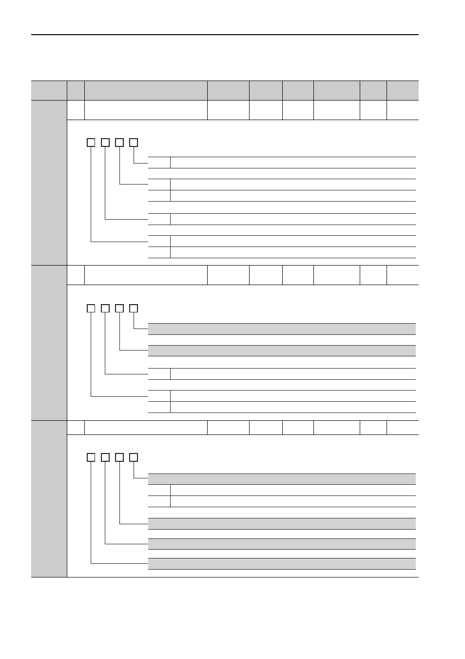
Pn82D
2
Option Field Allocation 4
0000 to
1F1C
–
0000
After restart
Setup
*1
Pn82E
2
Option Field Allocation 5
0000 to
1D1F
–
0000
After restart
Setup
*1
Pn833
2
Motion Setting
0000 to 0001
–
0000
After restart
Setup
*1
∗1. For details, refer to
Σ
-V Series User’s Manual MECHATROLINK-II Commands (No.: SIEP S800000 54).
(cont’d)
Parameter
No.
Size
Name
Setting
Range
Units
Factory
Setting
When
Enabled
Classi-
fication
Reference
Section
4th
digit
3rd
digit
2nd
digit
1st
digit
n.
0 to C
BANK_SEL1 bit position
0
1
Disables BANK_SEL1 bit allocation.
Enables BANK_SEL1 bit allocation.
0 to F
LT_DISABLE bit position
0
1
Disables LT_DISABLE bit allocation.
Enables LT_DISABLE bit allocation.
4th
digit
3rd
digit
2nd
digit
1st
digit
n.
0 to D
OUT_SIGNAL bit position
0
1
Disables OUT_SIGNAL bit allocation.
Enables OUT_SIGNAL bit allocation.
Reserved (Do not change.)
Reserved (Do not change.)
4th
digit
3rd
digit
2nd
digit
1st
digit
n.
Linear Accel/Decel Constant Selection
0
1
Uses Pn80A to Pn80F and Pn827. (Setting of Pn834 to Pn840 disabled)
Uses Pn834 to Pn840. (Setting of Pn80A to Pn80F and Pn827 disabled)
Reserved (Do not change.)
Reserved (Do not change.)
Reserved (Do not change.)