Cursor measurement, Manual mode, Cursor measurement -33 – RIGOL MSO/DS1000Z Series User Manual
Page 147: Manual mode -33
Chapter 6 MATH and Measurement
RIGOL
MSO1000Z/DS1000Z User’s Guide
6-33
Cursor Measurement
Cursor measurement can measure the X axis values (usually Time) and Y axis values
(usually Voltage) of the selected waveform. Before making cursor measurement,
connect the signal to the oscilloscope and acquire stable display. All the parameters
supported by the "Auto Measurement" function can be measured through cursors.
Press Cursor Mode at the front panel and use
to select the desired cursor
mode (the default is "OFF") and then press down the knob. The modes available are
"Manual", "Track" and "Auto". When the Time Base Mode is set to XY, you can
select the XY cursor measurement mode.
Manual Mode
In this mode, a pair of cursors will appear. You can adjust the cursors manually to
measure the X (or Y), X increment (or Y increment) between cursors and the reciprocal of
X increment on the waveform of the selected source (CH1-CH4, LA or MATH). When the
measurement source is set to LA, the logic level value of the digital channel currently
turned on will be displayed in hexadecimal forms (high level is 1 and low level is 0).
Press Cursor Mode "Manual" to turn the manual cursor function on. To easily
read data, the display form of measurement results on the upper left corner of the
screen changes with the measurement source and unit selected.
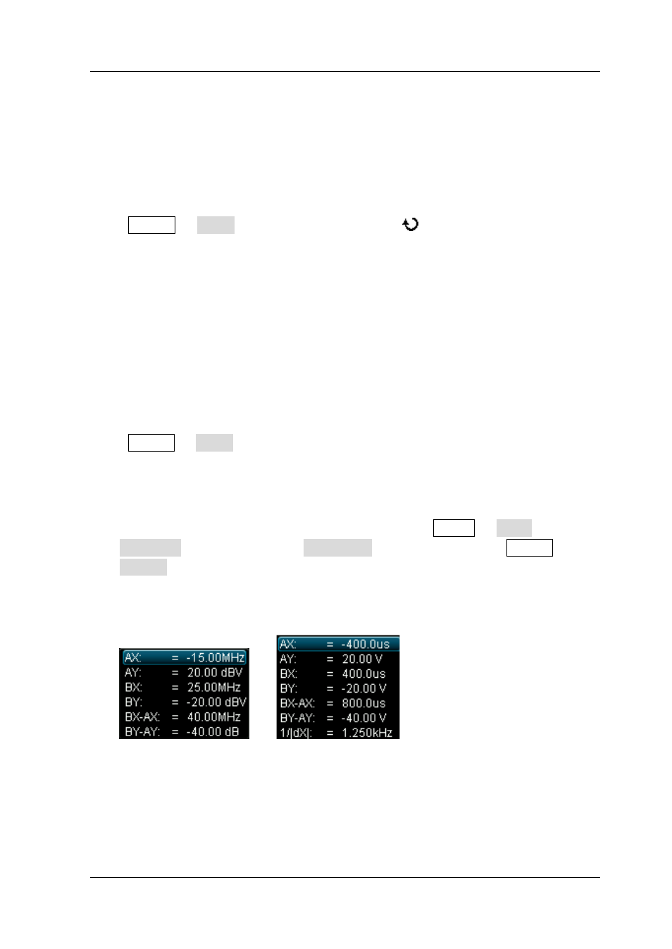
When the measurement source is set to CH1-CH4 or MATH:
When the measurement source is set to FFT (press MATH Math
Operator "FFT" and press Operation to select "ON"; press Cursor
Source "MATH") and the horizontal unit is set to "Hz", the form of the
measurement results is as shown in figure (a).
When the measurement source is non-FFT and the horizontal unit is set to "s",
the form of the measurement results is as shown in figure (b).
Figure (a) Figure (b)
AX: the X value at cursor A. X value takes the trigger position as reference. Its
unit is "s" or "Hz" (when measuring FFT waveform).
AY: the Y value at cursor A. Y value takes the channel GND of CH1 as reference.
Its unit is the same as that of the current signal source.
BX: the X value at cursor B. X value takes the trigger position as reference. Its
unit is "s" or "Hz" (when measuring FFT waveform).