Msi-x, Implementing msi-x interrupts – Altera Arria V Avalon-ST User Manual
Page 122
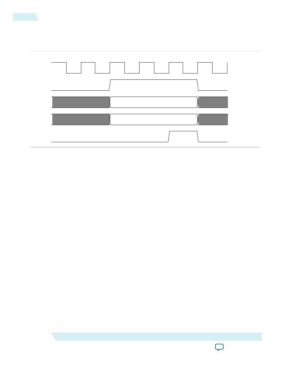
be deasserted before or within the same clock as
app_msi_ack
is deasserted to avoid inferring a new
interrupt.
Figure 7-4: MSI Interrupt Signals Timing
clk
app_msi_req
app_msi_tc[2:0]
app_msi_num[4:0]
app_msi_ack
1
2
3
5
6
4
7
valid
valid
Related Information
Correspondence between Configuration Space Registers and the PCIe Specification
MSI-X
You can enable MSI-X interrupts by turning on Implement MSI-X under the PCI Express/PCI Capabili‐
ties heading using the parameter editor. If you turn on the Implement MSI-X option, you should
implement the MSI-X table structures at the memory space pointed to by the BARs as part of your
Application Layer.
MSI-X TLPs are generated by the Application Layer and sent through the TX interface. They are single
dword memory writes so that
Last DW Byte Enable
in the TLP header must be set to 4b’0000. MSI-X
TLPs should be sent only when enabled by the MSI-X enable and the function mask bits in the message
control for MSI-X Configuration register. These bits are available on the
tl_cfg_ctl
output bus.
Related Information
•
•
Implementing MSI-X Interrupts
Section 6.8.2 of the PCI Local Bus Specification describes the MSI-X capability and table structures. The
MSI-X capability structure points to the MSI-X Table structure and MSI-X Pending Bit Array (PBA)
registers. The BIOS sets up the starting address offsets and BAR associated with the pointer to the starting
address of the MSI-X table and PBA registers.
The following figure shows the Application Layer modules that implement MSI-X interrupts.
7-4
MSI-X
2014.12.15
Altera Corporation
Interrupts