Transaction layer configuration space signals – Altera Arria V Avalon-ST User Manual
Page 71
Related Information
Transaction Layer Configuration Space Signals
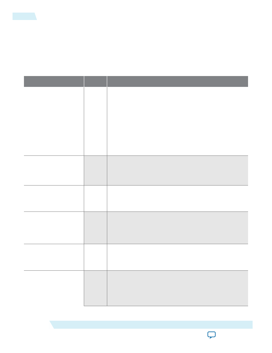
Table 4-12: Configuration Space Signals
These signals are not available if Configuration Space Bypass mode is enabled.
Signal
Direction
Description
tl_cfg_add[6:0]
0utput Address of the register that has been updated. This signal is an
index indicating which Configuration Space register information is
being driven onto
tl_cfg_ctl
. The indexing is defined in
Multiplexed Configuration Register Information Available on
tl_
cfg_ctl
. The index increments every 8
coreclkout
cycle. The
index increments every 8
coreclkout
cycles. The index consists of
the following 2 fields:
• [6:4] - indicates the function number whose information is
being presented on
tl_cfg_ctl
• [3:0] - the
tl_cfg_ctltl_cfg_ctl
multiplexor index
tl_cfg_ctl[31:0]
0utput The signal is multiplexed and contains the contents of the
Configuration Space registers. The indexing is defined in
Multiplexed Configuration Register Information Available on
tl_
cfg_ctl
.
tl_cfg_ctl_wr
0utput Write signal. This signal toggles when
tl_cfg_ctl
has been
updated (every 8
coreclkout
cycles). The toggle edge marks
where the
tl_cfg_ctl
data changes. You can use this edge as a
reference to determine when the data is safe to sample.
tl_cfg_sts[122:0]
0utput Configuration status bits. This information updates every
coreclkout
cycle. Bits[52:0] record status information for
function0. Bits[62:53] record information for function1.
Bits[72:63] record information for function 2, and so on. Refer to
the following table for a detailed description of the status bits.
tl_cfg_sts_wr
0utput Write signal. This signal toggles when
tl_cfg_sts
has been
updated (every 8 core_clk cycles). The toggle marks the edge where
tl_cfg_sts
data changes. You can use this edge as a reference to
determine when the data is safe to sample.
hpg_ctrler[4:0]
Input
The
hpg_ctrler
signals are only available in Root Port mode and
when the Slot capability register is enabled. Refer to the Slot
register and Slot capability register parameters in Table 6–9 on
page 6–10. For Endpoint variations the
hpg_ctrler
input should
be hardwired to 0s. The bits have the following meanings:
4-34
Transaction Layer Configuration Space Signals
2014.12.15
Altera Corporation
Interfaces and Signal Descriptions