Altera Arria V Avalon-ST User Manual
Page 184
Each subsequent descriptor consists of a minimum of four dwords of data and corresponds to one DMA
transfer. (A dword equals 32 bits.)
Note: The chaining DMA descriptor table should not cross a 4 KByte boundary.
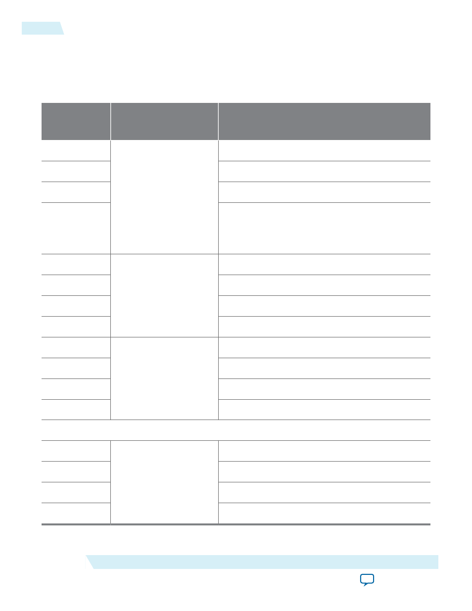
Table 16-7: Chaining DMA Descriptor Table
Byte Address
Offset to Base
Source
Descriptor Type
Description
0x0
Descriptor Header
Reserved
0x4
Reserved
0x8
Reserved
0xC
EPLAST - when enabled by the
EPLAST_ENA
bit in the
control register or descriptor, this location records the
number of the last descriptor completed by the chaining
DMA module.
0x10
Descriptor 0
Control fields, DMA length
0x14
Endpoint address
0x18
RC address upper dword
0x1C
RC address lower dword
0x20
Descriptor 1
Control fields, DMA length
0x24
Endpoint address
0x28
RC address upper dword
0x2C
RC address lower dword
. . .
0x ..0
Descriptor <n>
Control fields, DMA length
0x ..4
Endpoint address
0x ..8
RC address upper dword
0x ..C
RC address lower dword
16-14
Chaining DMA Descriptor Tables
2014.12.15
Altera Corporation
Testbench and Design Example