Figure 9-4: physical layer architecture – Altera Arria V Avalon-ST User Manual
Page 143
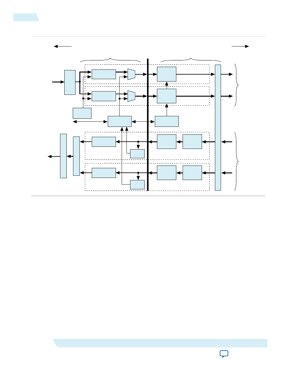
Figure 9-4: Physical Layer Architecture
Scrambler
8B10B
Encoder
Lane n
TX+ / TX-
Scrambler
8B10B
Encoder
Lane 0
TX+ / TX-
Descrambler
8B10B
Decoder
Lane n
RX+ / RX-
Elastic
Buffer
LTSSM
State Machine
SKIP
Generation
Control & Status
PIPE
Emulation Logic
Link S
erializ
er
for an x8 Link
TX Packets
RX MAC
Lane
D
evic
e
Transc
eiv
er (per L
ane) with 2.5 or 5.0 G
bps SERDES & PLL
Descrambler
8B10B
Decoder
Lane 0
RX+ / RX-
Elastic
Buffer
RX MAC
Lane
PIPE
Interface
Multilane D
esk
ew
Link S
erializ
er f
or an x8 Link
RX Packets
Transmit
Data Path
Receive
Data Path
MAC Layer
PHY layer
To Link
To Data Link Layer
The Physical Layer is subdivided by the PIPE Interface Specification into two layers (bracketed horizon‐
tally in above figure):
• Media Access Controller (MAC) Layer—The MAC layer includes the LTSSM and the scrambling/
descrambling and multilane deskew functions.
• PHY Layer—The PHY layer includes the 8B/10B and 128b/130b encode/decode functions, elastic
buffering, and serialization/deserialization functions.
The Physical Layer integrates both digital and analog elements. Intel designed the PIPE interface to
separate the MAC from the PHY. The Arria V Hard IP for PCI Express complies with the PIPE interface
specification.
9-10
Physical Layer
2014.12.15
Altera Corporation
IP Core Architecture