Adding an interface to a qinq tunnel, Figure 70: enabling qinq tunneling, Adding an – Microsens MS453490M Management Guide User Manual
Page 173
C
HAPTER
6
| VLAN Configuration
IEEE 802.1Q Tunneling
– 173 –
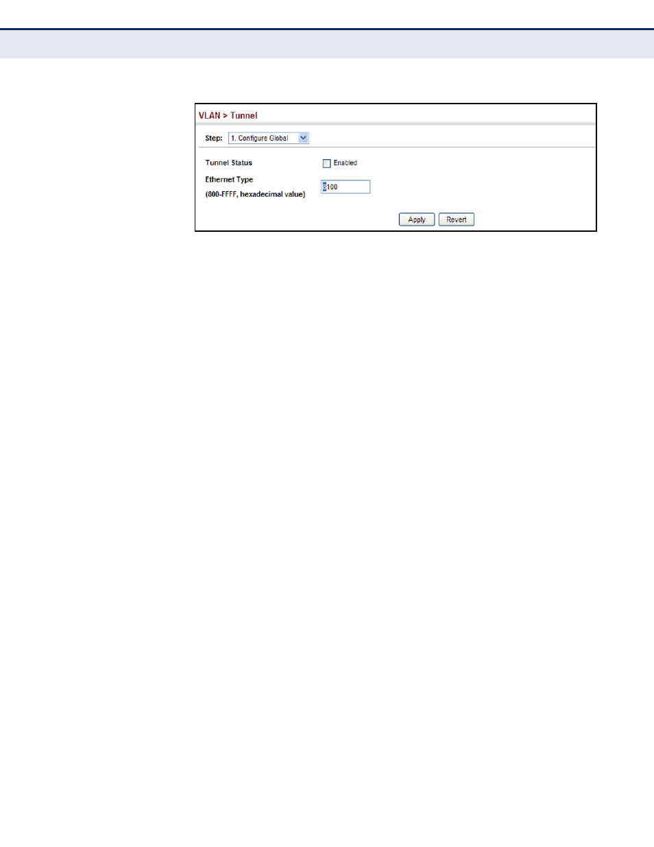
Figure 70: Enabling QinQ Tunneling
A
DDING
AN
I
NTERFACE
TO
A
Q
IN
Q T
UNNEL
Follow the guidelines in the preceding section to set up a QinQ tunnel on
the switch. Then use the VLAN > Tunnel (Configure Interface) page to set
the tunnel mode for any participating interface.
CLI R
EFERENCES
◆
"Configuring IEEE 802.1Q Tunneling" on page 796
C
OMMAND
U
SAGE
◆
Use the Configure Global page to set the switch to QinQ mode before
configuring a tunnel port or tunnel uplink port (see
Tunneling on the Switch" on page 172
). Also set the Tag Protocol
Identifier (TPID) value of the tunnel port if the attached client is using a
nonstandard 2-byte ethertype to identify 802.1Q tagged frames.
◆
Then use the Configure Interface page to set the access interface on
the edge switch to Tunnel mode, and set the uplink interface on the
switch attached to the service provider network to Tunnel Uplink mode.
P
ARAMETERS
These parameters are displayed:
◆
Interface – Displays a list of ports or trunks.
◆
Port – Port Identifier. (Range: 1-10)
◆
Trunk – Trunk Identifier. (Range: 1-5)
◆
Mode – Sets the VLAN membership mode of the port.
■
None – The port operates in its normal VLAN mode. (This is the
default.)
■
Tunnel – Configures QinQ tunneling for a client access port to
segregate and preserve customer VLAN IDs for traffic crossing the
service provider network.
■
Tunnel Uplink – Configures QinQ tunneling for an uplink port to
another device within the service provider network.