Configuration procedure – H3C Technologies H3C S12500 Series Switches User Manual
Page 117
101
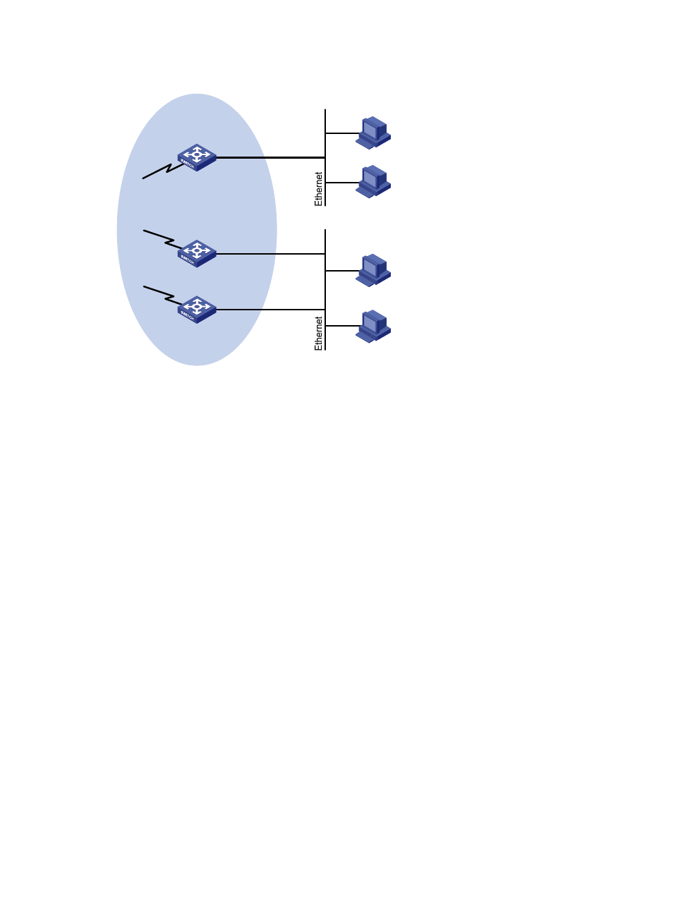
Figure 34 Network diagram
Configuration procedure
1.
Configure the IP address and subnet mask of each interface as shown in
shown.)
2.
Configure OSPF for interoperation on the PIM network to make sure that the network-layer is
interoperable on the PIM network and routing information among the switches can be dynamically
updated. (Details not shown.)
3.
Enable IP multicast routing, and enable PIM-DM and IGMP:
# Enable IP multicast routing on Switch A, enable PIM-DM on each interface, and enable IGMP on
VLAN-interface 100.
<SwitchA> system-view
[SwitchA] multicast routing-enable
[SwitchA] interface vlan-interface 100
[SwitchA-Vlan-interface100] igmp enable
[SwitchA-Vlan-interface100] pim dm
[SwitchA-Vlan-interface100] quit
[SwitchA] interface vlan-interface 101
[SwitchA-Vlan-interface101] pim dm
[SwitchA-Vlan-interface101] quit
# Enable IP multicast routing on Switch B, enable PIM-DM on each interface, and enable IGMP on
VLAN-interface 200.
<SwitchB> system-view
[SwitchB] multicast routing-enable
[SwitchB] interface vlan-interface 200
[SwitchB-Vlan-interface200] igmp enable
[SwitchB-Vlan-interface200] pim dm
[SwitchB-Vlan-interface200] quit
[SwitchB] interface vlan-interface 201
Switch A
Switch B
Switch C
Querier
PIM network
N1
N2
Receiver
Receiver
Host A
Host B
Host C
Host D
Vlan-int100
10.110.1.1/24
Vlan-int200
10.110.2.1/24
Vlan-int200
10.110.2.2/24
Vlan-int101
Vlan-int201
Vlan-int202