Configuring multicast vlans, Overview – H3C Technologies H3C S12500 Series Switches User Manual
Page 67
51
Configuring multicast VLANs
Overview
In this chapter, the switch functions as a Layer 2 device (referred to as the switch in network diagrams);
configurations for a Layer 3 device (referred to as the router in network diagrams) are implemented on
an H3C router.
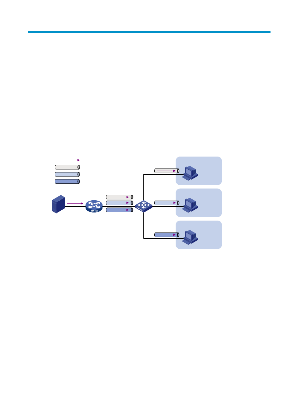
In the traditional multicast programs-on-demand mode shown in
, when hosts (Host A, Host B,
and Host C) that belong to different VLANs require multicast programs-on-demand service, the Layer 3
device (Router A) must forward a separate copy of the multicast traffic in each user VLAN to the Layer 2
device (Switch A). In this case, a large amount of network bandwidth is used and an extra burden is
added to the Layer 3 device.
Figure 20 Multicast transmission without the multicast VLAN feature
The multicast VLAN feature configured on the Layer 2 device is the solution to this issue. With the
multicast VLAN feature, the Layer 3 device replicates the multicast traffic only in the multicast VLAN
instead of making a separate copy of the multicast traffic in each user VLAN. This saves network
bandwidth and lessens the burden on the Layer 3 device.
The multicast VLAN feature can be implemented in a sub-VLAN-based multicast VLAN.
As shown in
, Host A, Host B, and Host C are in three different user VLANs. On Switch A,
configure VLAN 10 as a multicast VLAN, configure all user VLANs as sub-VLANs of this multicast VLAN,
and enable IGMP snooping in the multicast VLAN.
Source
Receiver
Host A
Multicast packets
VLAN 2
VLAN 3
VLAN 4
VLAN 2
VLAN 3
VLAN 4
Switch A
Receiver
Host B
Receiver
Host C
Router A
IGMP querier