Multicast forwarding over a gre tunnel, Network requirements, Configuration procedure – H3C Technologies H3C S12500 Series Switches User Manual
Page 93
77
RPF interface: Vlan-interface101, RPF neighbor: 20.1.1.2
Referenced route/mask: 50.1.1.0/24
Referenced route type: multicast static
Route selection rule: preference-preferred
Load splitting rule: disable
The output shows that the RPF routes to Source 2 exist on Switch B and Switch C. The routes are the
configured static routes.
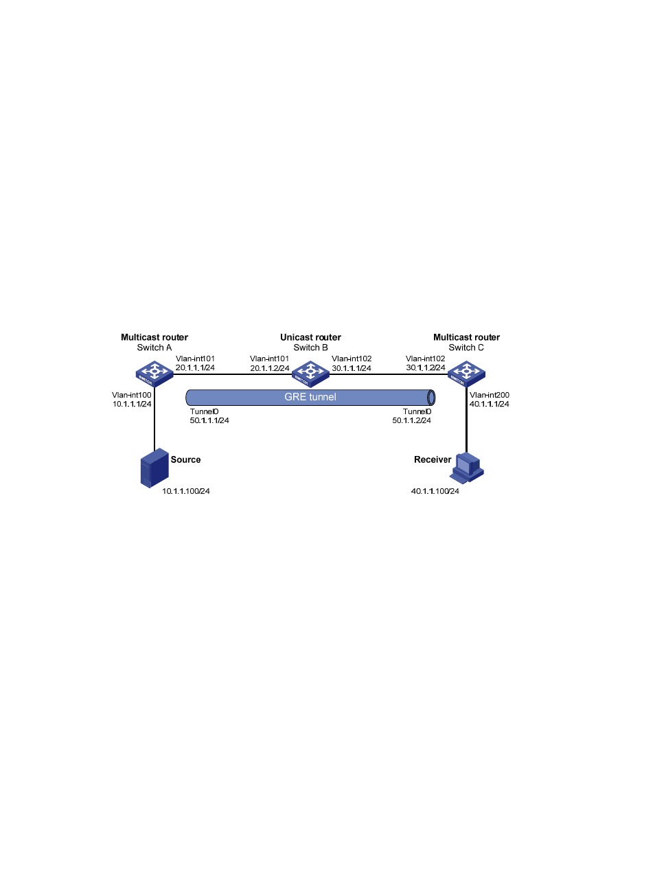
Multicast forwarding over a GRE tunnel
Network requirements
As shown in
, multicast routing and PIM-DM are enabled on Switch A and Switch C. Switch B
does not support multicast. OSPF is running on Switch A, Switch B, and Switch C.
Perform the following configurations so that Receiver can receive the multicast data from Source.
Figure 29 Network diagram
Configuration procedure
1.
Configure the IP address and subnet mask for each interface as shown in
shown.)
2.
Configure a GRE tunnel:
# Create Tunnel 0 on Switch A and configure the IP address and subnet mask for the interface.
<SwitchA> system-view
[SwitchA] interface tunnel 0
[SwitchA-Tunnel0] ip address 50.1.1.1 24
# Configure Tunnel 0 to operate in the GRE tunnel mode and specify the source and destination
addresses for the interface.
[SwitchA-Tunnel0] tunnel-protocol gre
[SwitchA-Tunnel0] source 20.1.1.1
[SwitchA-Tunnel0] destination 30.1.1.2
[SwitchA-Tunnel0] quit
# Create Tunnel 0 on Switch C and configure the IP address and subnet mask for the interface.
<SwitchC> system-view
[SwitchC] interface tunnel 0
[SwitchC-Tunnel0] ip address 50.1.1.2 24