Verifying the configuration, Creating an rpf route, Network requirements – H3C Technologies H3C S12500 Series Switches User Manual
Page 91: Configuration procedure
75
[SwitchB] ip rpf-route-static 50.1.1.100 24 20.1.1.2
Verifying the configuration
# Use the display multicast rpf-info command to view the information about the RPF route to Source
on Switch B.
[SwitchB] display multicast rpf-info 50.1.1.100
RPF information about source 50.1.1.100:
RPF interface: Vlan-interface101, RPF neighbor: 20.1.1.2
Referenced route/mask: 50.1.1.0/24
Referenced route type: multicast static
Route selection rule: preference-preferred
Load splitting rule: disable
The output shows that the RPF route on Switch B has changed. It is now the configured static
multicast route, and the RPF neighbor is now Switch C.
Creating an RPF route
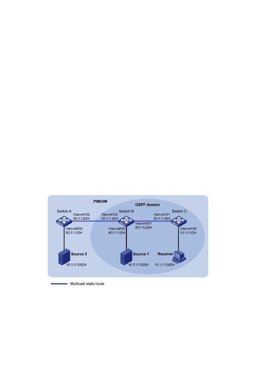
Network requirements
As shown in
, PIM-DM runs in the network and all switches in the network support IP multicast.
Switch B and Switch C run OSPF, and have no unicast routes to Switch A. Typically, Receiver can receive
the multicast data from Source 1 in the OSPF domain.
Perform the following configuration so that Receiver can receive multicast data from Source 2, which is
outside the OSPF domain.
Figure 28 Network diagram
Configuration procedure
1.
Configure the IP address and subnet mask for each interface as shown in
shown.)
2.
Enable OSPF on Switch B and Switch C to make sure the network-layer is interoperable between
Switch B and Switch C and their routing information can be dynamically updated. (Details not
shown.)
3.
Enable IP multicast routing, and enable PIM-DM and IGMP: