Multicast vlan configuration example, Network requirements, Configuration procedure – H3C Technologies H3C S12500 Series Switches User Manual
Page 70
54
Multicast VLAN configuration example
IMPORTANT:
By default, Ethernet interfaces, VLAN interfaces, and aggregate interfaces are in the state of DOWN. To
configure such an interface, use the undo shutdown commands to bring it up first.
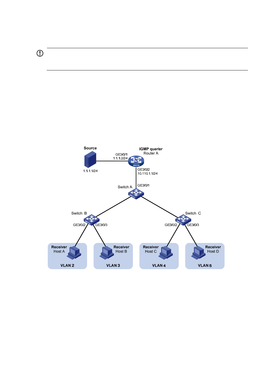
Network requirements
As shown in
, IGMPv2 runs on Router A, and IGMPv2 snooping runs on Switch A, Switch B,
and Switch C. Router A acts as the IGMP querier.
The multicast source sends multicast data to multicast group 224.1.1.1. Host A, Host B, Host C, and Host
D are receivers of the multicast group. The hosts belong to VLAN 2 through VLAN 5.
Configure the sub-VLAN-based multicast VLAN feature on Switch A so that Router A just sends multicast
data to Switch A through the multicast VLAN and Switch A forwards the traffic to the receivers that belong
to different user VLANs.
Figure 22 Network diagram
Configuration procedure
1.
Configure an IP address and subnet mask for each interface as per
2.
On Router A, enable IP multicast routing, enable PIM-DM on each Layer 3 interface, and enable
IGMP on the host-side interface GigabitEthernet 3/0/2.
<RouterA> system-view
[RouterA] multicast routing-enable
[RouterA] interface GigabitEthernet 3/0/1
[RouterA-GigabitEthernet3/0/1]port link-mode route
[RouterA-GigabitEthernet3/0/1] pim dm
GE
3/0
/2
GE3
/0/3
GE
3/0
/1
GE3
/0/1