Configuration procedure – H3C Technologies H3C S12500 Series Switches User Manual
Page 287
271
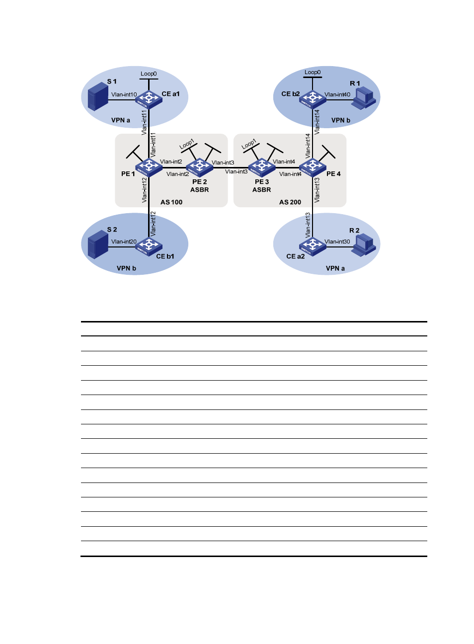
Figure 77 Network diagram
shows the interface and IP address assignment, and network topology scheme.
Table 20 Interface and IP address assignment
Device Interface
IP
address
Device
Interface
IP address
S 1
—
10.11.5.2/24
R 1
—
10.11.8.2/24
S 2
—
10.11.6.2/24
R 2
—
10.11.7.2/24
PE 1
Vlan-int2
10.10.1.1/24
PE 3
Vlan-int4
10.10.2.1/24
PE 1
Vlan-int11
10.11.1.1/24
PE 3
Vlan-int3
192.168.1.2/24
PE 1
Vlan-int12
10.11.2.1/24
PE 3
Loop1
1.1.1.3/32
PE 1
Loop1
1.1.1.1/32
PE 3
Loop2
22.22.22.22/32
PE 2
Vlan-int2
10.10.1.2/24
PE 4
Vlan-int4
10.10.2.2/24
PE 2
Vlan-int3
192.168.1.1/24
PE 4
Vlan-int13
10.11.3.1/24
PE 2
Loop1
1.1.1.2/32
PE 4
Vlan-int14
10.11.4.1/32
PE 2
Loop2
11.11.11.11/32
PE 4
Loop2
1.1.1.4/32
CE a1
Vlan-int10
10.11.5.1/24
CE b1
Vlan-int20
10.11.6.1/24
CE a1
Vlan-int11
10.11.1.2/24
CE b1
Vlan-int12
10.11.2.2/24
CE a1
Loop0
2.2.2.2/32
CE b2
Vlan-int40
10.11.8.1/24
CE a2
Vlan-int30
10.11.7.1/24
CE b2
Vlan-int14
10.11.4.2/24
CE a2
Vlan-int13
10.11.3.2/24
CE b2
Loop0
3.3.3.3/32
Configuration procedure
1.
Configure PE 1:
Loop
2
Loop
2
Loop1
Lo
op
1