Pim-sm inter-domain multicast configuration, Network requirements – H3C Technologies H3C S12500 Series Switches User Manual
Page 215
199
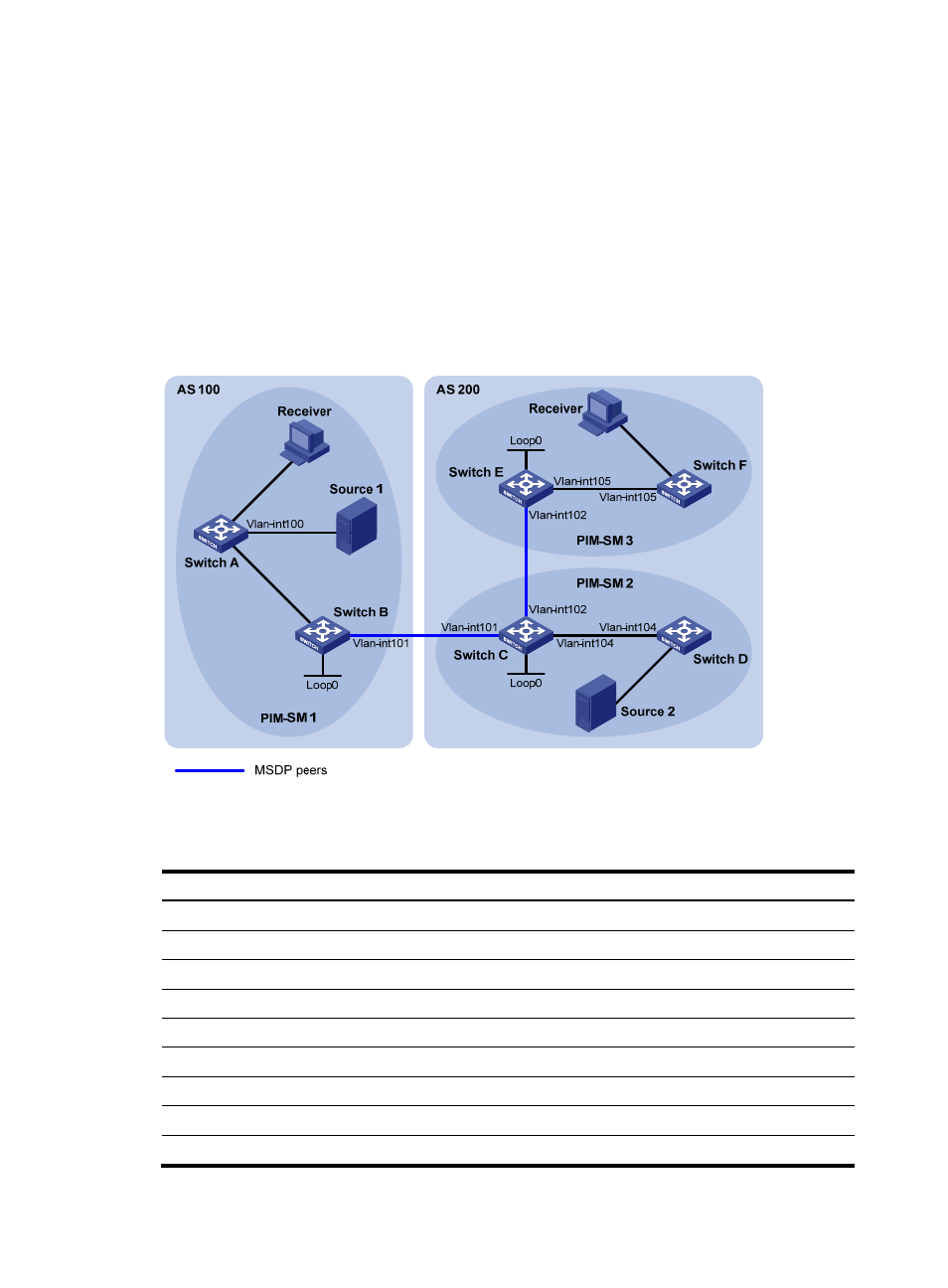
PIM-SM inter-domain multicast configuration
Network requirements
As shown in
, BGP runs between the two ASs. PIM-SM 1 belongs to AS 100, and PIM-SM 2 and
PIM-SM 3 belong to AS 200. Each PIM-SM domain has at least one multicast source or receiver.
Configure Loopback 0 as the C-BSR and C-RP of the related PIM-SM domain on Switch B, Switch C, and
Switch E.
Set up MSDP peering relationship between the RPs of the PIM-SM domains to share multicast source
information among the PIM-SM domains.
Figure 59 Network diagram
shows the interface and IP address assignment, and network topology scheme.
Table 14 Interface and IP address assignment
Device Interface IP
address
Device
Interface
IP address
Switch A
Vlan-int103
10.110.1.2/24
Switch D
Vlan-int104
10.110.4.2/24
Switch A
Vlan-int100
10.110.2.1/24
Switch D
Vlan-int300
10.110.5.1/24
Switch A
Vlan-int200
10.110.3.1/24
Switch E
Vlan-int105
10.110.6.1/24
Switch B
Vlan-int103
10.110.1.1/24
Switch E
Vlan-int102
192.168.3.2/24
Switch B
Vlan-int101
192.168.1.1/24
Switch E
Loop0
3.3.3.3/32
Switch B
Loop0
1.1.1.1/32
Switch F
Vlan-int105
10.110.6.2/24
Switch C
Vlan-int104
10.110.4.1/24
Switch F
Vlan-int400
10.110.7.1/24
Switch C
Vlan-int102
192.168.3.1/24
Source 1
—
10.110.2.100/24
Switch C
Vlan-int101
192.168.1.2/24
Source 2
—
10.110.5.100/24
Vlan-
int10
3
Vl
an-
int10
3
Vlan-
int2
00
Vl
an-
int
300
Vl
an
-int400