Pim-ssm configuration example, Network requirements – H3C Technologies H3C S12500 Series Switches User Manual
Page 195
179
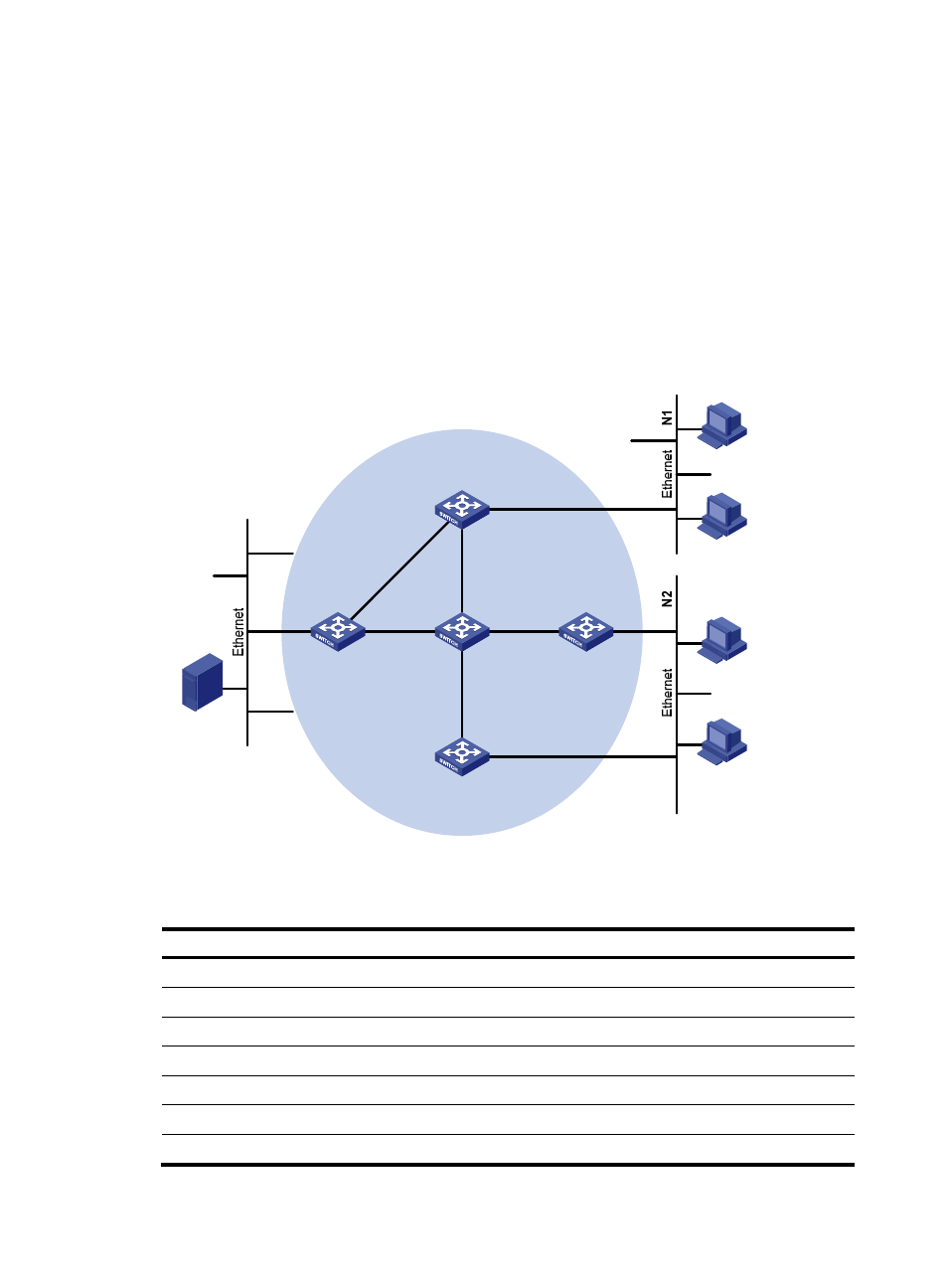
PIM-SSM configuration example
Network requirements
As shown in
, receivers receive VOD information through multicast. The receiver groups of
different organizations form stub networks, and one or more receiver hosts exist in each stub network. The
entire PIM domain operates in the SSM mode.
Host A and Host C are multicast receivers in two stub networks.
The SSM group range is 232.1.1.0/24.
IGMPv3 runs between Switch A and N1, and between Switch B/Switch C and N2.
Figure 54 Network diagram
shows the interface and IP address assignment, and network topology scheme.
Table 13 Interface and IP address assignment
Device Interface
IP address
Switch A
VLAN-interface 100
10.110.1.1/24
Switch A
VLAN-interface 101
192.168.1.1/24
Switch A
VLAN-interface 102
192.168.9.1/24
Switch B
VLAN-interface 200
10.110.2.1/24
Switch B
VLAN-interface 103
192.168.2.1/24
Switch C
VLAN-interface 200
10.110.2.2/24
Switch C
VLAN-interface 104
192.168.3.1/24
Source
10.110.5.100/24
PIM-SSM
Switch A
Switch B
Switch C
Switch D
Receiver
Host A
Host B
Host C
Host D
Receiver
Switch E
Vlan-int100
Vlan-int200
Vlan-int200
Vlan-int300
Vlan-int102
Vlan-int102
Vlan-
int101
Vlan-
int
101
Vlan-int103
Vlan-int103
Vlan-int104
Vlan-int104
Vlan-int105
Vlan-int105