Pim-sm non-scoped zone configuration example, Network requirements – H3C Technologies H3C S12500 Series Switches User Manual
Page 178
162
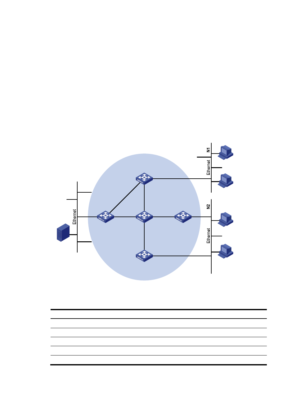
PIM-SM non-scoped zone configuration example
Network requirements
As shown in
, receivers receive VOD information through multicast. The receiver groups of
different organizations form stub networks, and one or more receiver hosts exist in each stub network. The
entire PIM-SM domain contains only one BSR.
Host A and Host C are multicast receivers in two stub networks.
VLAN-interface 105 on Switch D and VLAN-interface 102 on Switch E act as C-BSRs and C-RPs; the
C-BSR on Switch E has a higher priority; the multicast group range to which the C-RP is designated is
225.1.1.0/24; modify the hash mask length to map a certain number of consecutive group addresses
within the range to the two C-RPs.
IGMPv2 runs between Switch A and N1, and between Switch B/Switch C and N2.
Figure 51 Network diagram
shows the interface and IP address assignment, and network topology scheme.
Table 10 Interface and IP address assignment
Device Interface
IP address
Switch A
VLAN-interface 100
10.110.1.1/24
Switch A
VLAN-interface 101
192.168.1.1/24
Switch A
VLAN-interface 102
192.168.9.1/24
Switch B
VLAN-interface 200
10.110.2.1/24
Switch B
VLAN-interface 103
192.168.2.1/24
Source
10.110.5.100/24
PIM-SM
Switch A
Switch B
Switch C
Switch D
Receiver
Host A
Host B
Host C
Host D
Receiver
Switch E
Vlan-int100
Vlan-int200
Vlan-int200
Vlan-int300
Vlan-int102
Vlan-int102
Vlan-
int
101
Vlan-
int10
1
Vlan-int103
Vlan-int103
Vlan-int104
Vlan-int104
Vlan-int105
Vlan-int105