Configuration procedure – H3C Technologies H3C S12500 Series Switches User Manual
Page 421
405
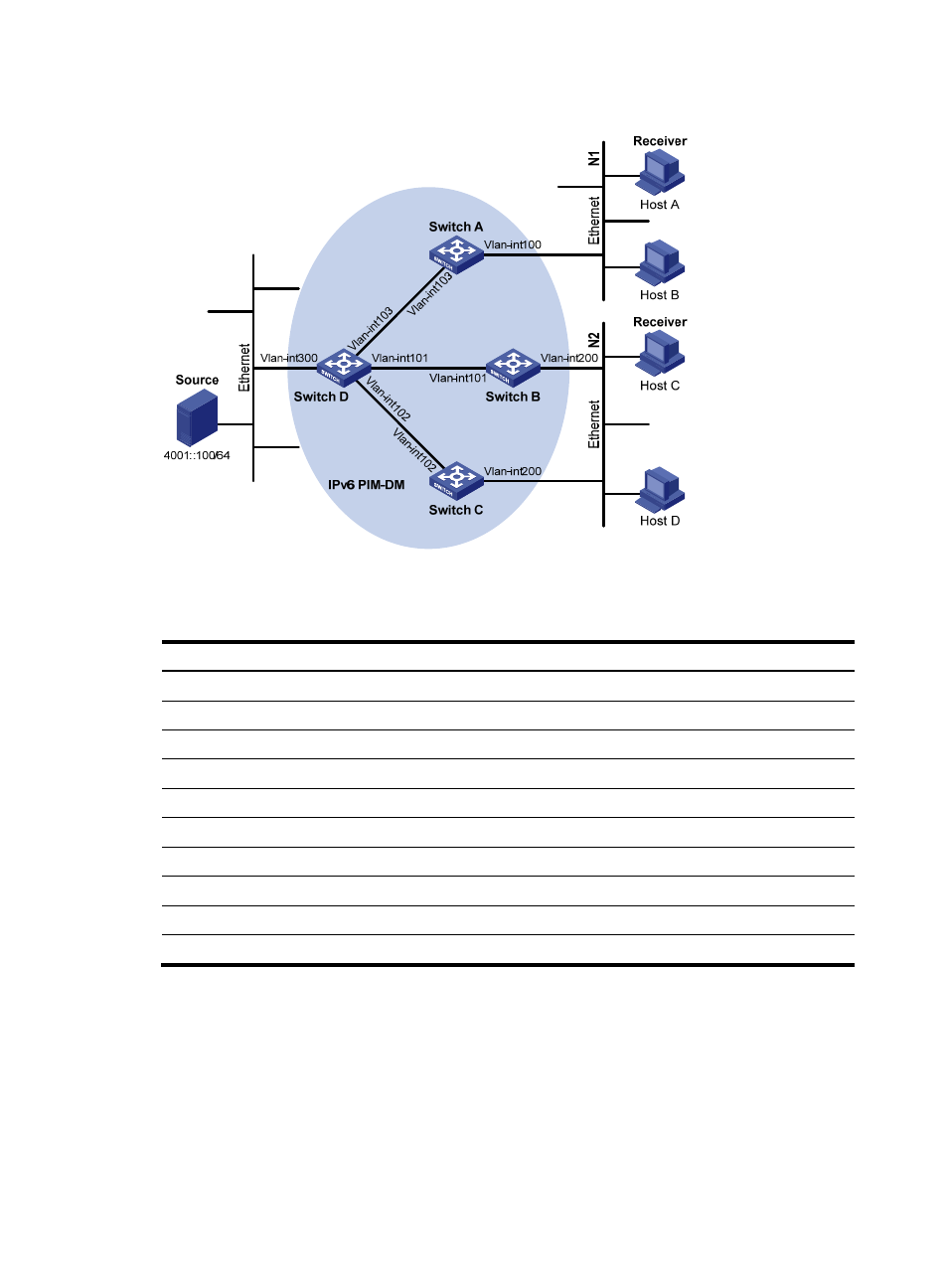
Figure 109 Network diagram
shows the interface and IPv6 address assignment, and network topology scheme.
Table 27 Interface and IPv6 address assignment
Device Interface
IPv6 address
Switch A
VLAN-interface 100
1001::1/64
Switch A
VLAN-interface 103
1002::1/64
Switch B
VLAN-interface 200
2001::1/64
Switch B
VLAN-interface 101
2002::1/64
Switch C
VLAN-interface 200
2001::2/64
Switch C
VLAN-interface 102
3001::1/64
Switch D
VLAN-interface 300
4001::1/64
Switch D
VLAN-interface 103
1002::2/64
Switch D
VLAN-interface 101
2002::2/64
Switch D
VLAN-interface 102
3001::2/64
Configuration procedure
1.
Enable IPv6 forwarding on each switch and configure the IPv6 address and prefix length for each
interface as per
. (Details not shown.)
2.
Configure OSPFv3 on the switches in the IPv6 PIM-DM domain to ensure network-layer
reachability among them. (Details not shown.)
3.
Enable IPv6 multicast routing, and enable IPv6 PIM-DM and MLD:
# Enable IPv6 multicast routing on Switch A, enable IPv6 PIM-DM on each interface, and enable
MLD on VLAN-interface 100, which connects Switch A to N1.