Configuration procedure – H3C Technologies H3C S12500 Series Switches User Manual
Page 190
174
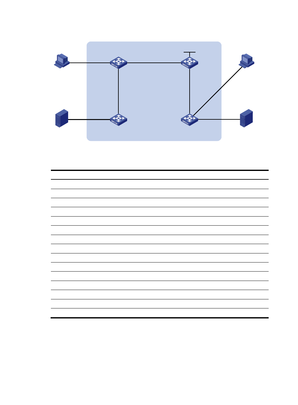
Figure 53 Network diagram
shows the interface and IP address assignment, and network topology scheme.
Table 12 Interface and IP address assignment
Device Interface
IP address
Switch A
VLAN-interface 100
192.168.1.1/24
Switch A
VLAN-interface 101
10.110.1.1/24
Switch B
VLAN-interface 200
192.168.2.1/24
Switch B
VLAN-interface 101
10.110.1.2/24
Switch B
VLAN-interface 102
10.110.2.1/24
Switch C
VLAN-interface 102
10.110.2.2/24
Switch C
VLAN-interface 103
10.110.3.1/24
Switch C
Loopback 0
1.1.1.1/32
Switch D
VLAN-interface 300
192.168.3.1/24
Switch D
VLAN-interface 400
192.168.4.1/24
Switch D
VLAN-interface 103
10.110.3.2/24
Source 1
—
192.168.1.100/24
Source 2
—
192.168.4.100/24
Receiver 1
—
192.168.2.100/24
Receiver 2
—
192.168.3.100/24
Configuration procedure
1.
Configure an IP address and subnet mask for each interface as per
2.
Configure OSPF on the switches in the BIDIR-PIM domain to ensure network-layer reachability
among them. (Details not shown.)
3.
Enable IP multicast routing, PIM-SM, BIDIR-PIM, and IGMP:
BIDIR-PIM
Source 1
Source 2
Host A
Receiver 1
Switch A
Vlan-int101
Vlan-int101
Vlan-int102
Vlan-int102
Vlan-int103
Vlan-int103
Vlan-int100
Vlan-int200
Vlan-
int300
Vlan-int400
Switch D
Switch C
Switch B
Host B
Receiver 2
Loop0