Configuration procedure – H3C Technologies H3C S12500 Series Switches User Manual
Page 175
159
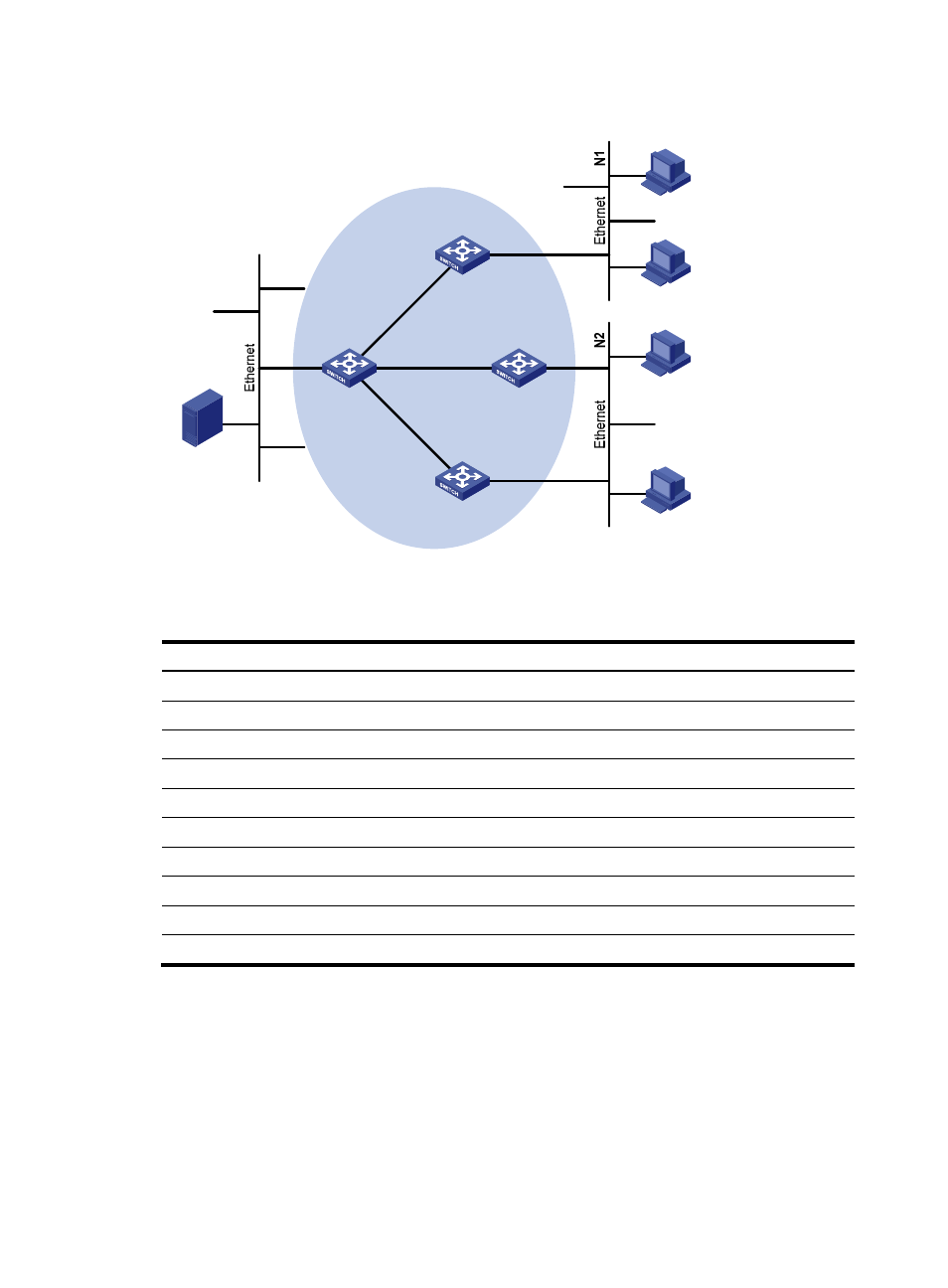
Figure 50 Network diagram
shows the interface and IP address assignment, and network topology scheme.
Table 9 Interface and IP address assignment
Device Interface
IP address
Switch A
VLAN-interface 100
10.110.1.1/24
Switch A
VLAN-interface 103
192.168.1.1/24
Switch B
VLAN-interface 200
10.110.2.1/24
Switch B
VLAN-interface 101
192.168.2.1/24
Switch C
VLAN-interface 200
10.110.2.2/24
Switch C
VLAN-interface 102
192.168.3.1/24
Switch D
VLAN-interface 300
10.110.5.1/24
Switch D
VLAN-interface 103
192.168.1.2/24
Switch D
VLAN-interface 101
192.168.2.2/24
Switch D
VLAN-interface 102
192.168.3.2/24
Configuration procedure
1.
Configure the IP address and subnet mask for each interface as per
. (Details not shown.)
2.
Configure OSPF on the switches in the PIM-DM domain to ensure network-layer reachability
among them. (Details not shown.)
3.
Enable IP multicast routing, and enable PIM-DM and IGMP:
# Enable IP multicast routing on Switch A, enable PIM-DM on each interface, and enable IGMP on
VLAN-interface 100, which connects Switch A to the stub network.
<SwitchA> system-view
Source
10.110.5.100/24
PIM-DM
Switch A
Switch B
Switch C
Switch D
Receiver
Host A
Host B
Host C
Host D
Receiver
Vlan-int100
Vlan-int200
Vlan-int200
Vlan-int300
Vlan-int101
Vlan-int101
Vlan-
int1
02
Vlan-
int1
02
Vlan-
int1
03
Vlan-
int10
3