Configuration procedure – H3C Technologies H3C S12500 Series Switches User Manual
Page 320
304
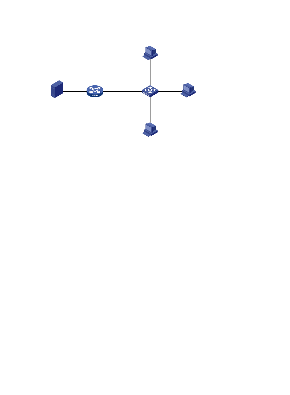
Figure 81 Network diagram
Configuration procedure
1.
Enable IPv6 forwarding and configure an IPv6 address and prefix length for each interface as
shown in
. (Details not shown.)
2.
On Router A, enable IPv6 multicast routing, enable IPv6 PIM-DM on each interface, and enable
MLDv1 on GigabitEthernet 3/1/1.
<RouterA> system-view
[RouterA] multicast ipv6 routing-enable
[RouterA] interface GigabitEthernet 3/1/1
[RouterA-GigabitEthernet3/1/1] mld enable
[RouterA-GigabitEthernet3/1/1] pim ipv6 dm
[RouterA-GigabitEthernet3/1/1] quit
[RouterA] interface Gigabitethernet 3/1/2
[RouterA-GigabitEthernet3/1/2] pim ipv6 dm
[RouterA-GigabitEthernet3/1/2] quit
3.
Configure Switch A:
# Enable MLD snooping globally.
<SwitchA> system-view
[SwitchA] mld-snooping
[SwitchA-mld-snooping] quit
# Create VLAN 100, assign GigabitEthernet 3/0/1 through GigabitEthernet 3/0/4 to this VLAN,
and enable MLD snooping and the function of dropping IPv6 unknown multicast traffic in the
VLAN.
[SwitchA] vlan 100
[SwitchA-vlan100] port GigabitEthernet 3/0/1 to GigabitEthernet 3/0/4
[SwitchA-vlan100] mld-snooping enable
[SwitchA-vlan100] mld-snooping drop-unknown
[SwitchA-vlan100] quit
# Configure an IPv6 multicast group filter so that the hosts in VLAN 100 can join only the IPv6
multicast group FF1E::101.
[SwitchA] acl ipv6 number 2001
Source
Router A
Switch A
Receiver
Receiver
Host B
Host A
Host C
GE3/0/1
GE3/0/4
GE3/0/2
GE3/0/3
MLD querier
1::1/64
GE3/1/1
2001::1/64
GE3/1/2
1::2/64