Sa message filtering configuration, Network requirements – H3C Technologies H3C S12500 Series Switches User Manual
Page 228
212
Total number of downstreams: 1
1: Vlan-interface200
Protocol: pim-sm, UpTime: - , Expires: -
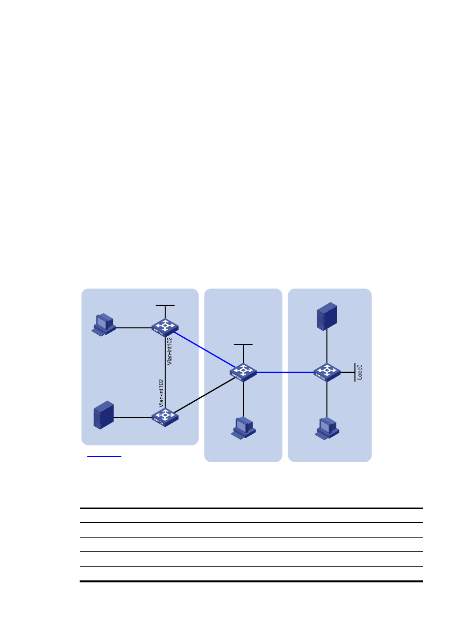
SA message filtering configuration
Network requirements
As shown in
, three PIM-SM domains exist in the network, and OSPF runs within and among the
domains to provide unicast routing.
Configure Loopback 0 of Switch A, Switch C, and Switch D as a C-BSR and C-RP in the respective
PIM-SM domain.
Set up an MSDP peering relationship between Switch A and Switch C and between Switch C and Switch
D.
Source 1 sends multicast data to multicast groups 225.1.1.0/30 and 226.1.1.0/30, and Source 2 sends
multicast data to multicast group 227.1.1.0/30.
Configure SA message filtering rules so that receivers Host A and Host B can receive only the multicast
data addressed to multicast groups 225.1.1.0/30 and 226.1.1.0/30, and Host can receive only the
multicast data addressed to multicast groups 226.1.1.0/30 and 227.1.1.0/30.
Figure 62 Network diagram
shows the interface and IP address assignment, and network topology scheme.
Table 17 Interface and IP address assignment
Device Interface
IP address
Source 1
—
10.110.3.100/24
Source 2
—
10.110.6.100/24
Switch A
VLAN-interface 100
10.110.1.1/24
Switch A
VLAN-interface 102
10.110.2.1/24
MSDP peers
PIM-SM 1
PIM-SM 2
PIM-SM 3
Loop0
Loop0
Source 1
Source 2
Receiver
Host B
Receiver
Host C
Receiver
Host A
Vlan-int100
Vlan-int200
Switch A
Switch C
Switch D
Switch B
Vla
n-in
t10
3
Vla
n-in
t10
3
Vlan
-int1
01
Vlan
-int1
01
Vlan-int300
Vlan-int104
Vlan-int104
Vlan-int500
Vlan-int400