Figure 4.15) – Verilink WANsuite 5130 (34-00298.L) Product Manual User Manual
Page 147
V T 1 0 0 I n t e r f a c e
4-19
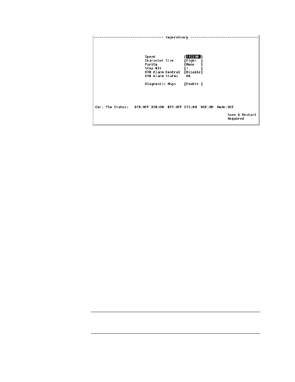
Figure 4.15
Supervisory Configuration Screen
Speed
Changes the Supervisory port speed (in bits per second).
Values: 1200, 2400, 4800, 9600, 19200, 38400, 57600, 115200
Default: 19200
Character Size
Selects the number of bits required to make up one asynchronous character.
Values: Five, Six, Seven, Eight
Default: Eight
Parity
Sets the parity bit.
Values: None, Odd, Even
Default: None
Stop Bit
Selects the number of bits required to end the character.
Values: 1, 2
Default: 1
DTR Alarm Control
Lets you set DTR Alarm Control parameters. Selecting “Enable” allows the
unit to go into alarm on loss of DTR, which occurs when the Supervisory port
detects that the DTR signal is low.
Values: Enable, Disable
Default: Disable
DTR Alarm Status
Lets you view the current DTR Alarm status.
Diagnostic Messages
Enables the Supervisory port to send out diagnostic messages upon power-up.
Values: Enable, Disable
Default: Enable
NOTICE:
When in SCADA mode, these diagnostic messages disrupt the connected
device. Therefore, if using the SCADA mode, set this value to
“Disable.”