Pfdena, Parameter settings, Summary of advanced control signals – Altera ALTPLL (Phase-Locked Loop) IP Core User Manual
Page 13
You should include the
areset
signal in your designs if any of the following conditions hold:
• PLL reconfiguration or clock switchover is enabled in your design.
• Phase relationships between the PLL input and output clocks must be maintained after a loss-of-lock
condition.
• The input clock to the PLL is not toggling or is unstable at power-up.
• Assert the
areset
signal after the input clock is toggling while staying within the input jitter specification.
pfdena
The
pfdena
signal enables or disables the PFD circuit. The PFD circuit is enabled by default. When the PFD
circuit is disabled, the PLL output does not depend on the input clock, and tends to drift outside of the lock
window. By default, the
pfdena
signal is tied to VCC internally.
Parameter Settings
For devices that support the advanced control signals—
pllena
,
pfdena
, and
areset
, the parameter settings
for these signals are located on the Inputs/Lock or Scan/Inputs/Lock page of the ALTPLL parameter editor.
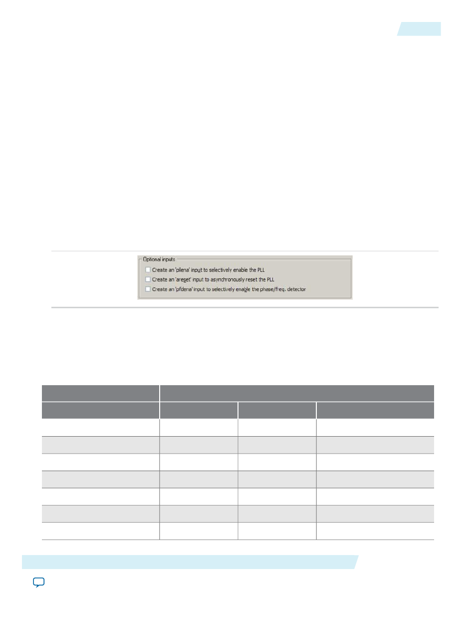
The following figure shows the options related to the advanced control signals. Turn on the control signal
you want to create from the options available.
Figure 8: Options to Select the Advanced Control Signals
The deassertion of the
pllena
signal or the assertion of the
areset
signal does not disable the VCO, but
instead resets the VCO to its nominal value. The only time that the VCO is completely disabled is when you
do not have a PLL instantiated in your design.
Summary of Advanced Control Signals
The following table summarizes the device families support for advanced control signals.
Supported Advanced Signals
Device Family
areset
pfdena
pllena
Yes
Yes
Yes
Arria GX
Yes
Yes
—
Arria II GX
Yes
Yes
—
Stratix IV
Yes
Yes
—
Stratix III
Yes
Yes
Yes
Stratix II
Yes
Yes
Yes
Stratix II GX
Yes
Yes
Yes
Stratix
Altera Corporation
ALTPLL (Phase-Locked Loop) IP Core User Guide
13
pfdena
ug-altpll
2014.08.18