Self-reset on loss of lock, Parameter settings – Altera ALTPLL (Phase-Locked Loop) IP Core User Manual
Page 19
use a gated lock signal. A gated
locked
signal or an ungated
locked
signal can feed a logic array or an output
pin. When you must reset the gated counter, reset the PLL by asserting the
areset
signal or the
pllena
signal.
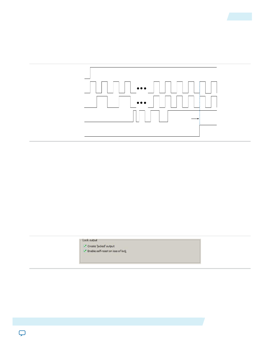
The following figure shows the timing waveform for gated and ungated locked signals.
Figure 11: Input and Output Ports
Feedback Clock
Locked
Reference Clock
PLLENA
Gated Lock
Filter Counter
Reaches
Value Count
Self-Reset on Loss of Lock
This feature allows the PLL to self-reset upon loss of lock, normally for the same reasons described in
on page 18
Related Information
on page 18
Parameter Settings
To enable the
locked
signal, and the self-reset feature in the ALTPLL IP core, use the parameter settings on
the Scan/Inputs/Lock or Inputs/Lock page of the ALTPLL parameter editor.
The following figure shows the related options in the Scan/Inputs/Lock or Inputs/Lock page for an
Arria II GX device. Note that the options are device-dependent and what you see may differ.
Figure 12: Lock Output Options
Turning on Create 'locked' output creates an output port named
locked
in the ALTPLL IP core.
Turning on Enable self-reset on loss of lock enables the self-reset feature.
In devices that support gated lock, another option appears on the page, which is the Hold 'locked' output
option. Turning on this option enables the gated lock circuitry to gate the
locked
signal. You must specify
the number of PLL input clock cycles to hold the
locked
signal low after the PLL is initialized. This value is
used by the gated lock counter. The value ranges from 1 to 1,048,575 clock cycles.
Altera Corporation
ALTPLL (Phase-Locked Loop) IP Core User Guide
19
Self-Reset on Loss of Lock
ug-altpll
2014.08.18