Implementing the shift_clk design – Altera ALTPLL (Phase-Locked Loop) IP Core User Manual
Page 67
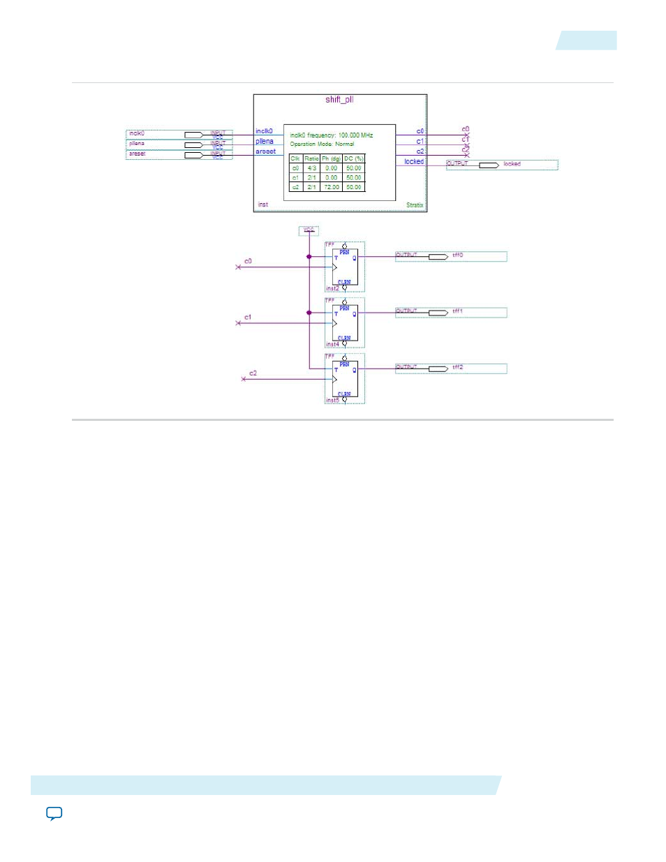
Figure 30: ALTPLL shift_pll Design Schematic
Implementing the shift_clk Design
To assign the EP1S10F780C5 device to the project and compile the project, follow these steps:
1. On the Assignments menu, click Settings. The Settings dialog box appears.
2. In the Category list, click Device. Select Stratix in the Device Family field.
3. In the Target device section, under the Available devices list, select EP1S10F780C5.
4. Click OK.
5. On the Processing menu, click Start Simulation.
6. When the Full Compilation was successful message box appears, click OK.
7. To view how the module is implemented in the Stratix device, from the Assignments menu, click Timing
Closure Floorplan.
The
shift_clk
design is now implemented.
Simulating the shift_clk Design in the ModelSim-Altera Software
This ModelSim design example is for the ModelSim-Altera (Verilog) version. To simulate the design in the
ModelSim-Altera software, follow these steps:
1. Download and unzip the
fileto any working directory on your PC.
2. Locate the folder in which you unzipped the files to, and open the shift_clk.do file in a text editor.
3. In line 1 of the shift_clk.do file, replace <insert_directory_path_here> with the directory path of the
appropriate library files. For example,
C:/Modeltech_ae/altera/verilog/stratix
.
Altera Corporation
ALTPLL (Phase-Locked Loop) IP Core User Guide
67
Implementing the shift_clk Design
ug-altpll
2014.08.18