Calculating the value of gated lock counter, Programmable bandwidth – Altera ALTPLL (Phase-Locked Loop) IP Core User Manual
Page 20
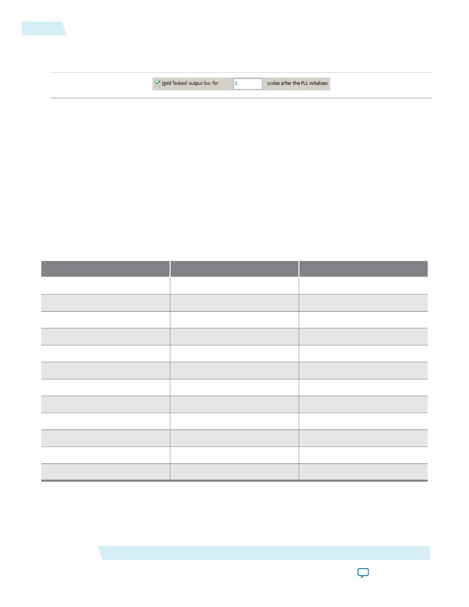
The following figure shows the Hold Locked Output option.
Figure 13: Hold Locked Output Option
Calculating the Value of Gated Lock Counter
To calculate the number of clock cycles needed, you must know the maximum lock time of the PLL, and the
period of the PLL input clock. The lock time of the PLL is listed in the “PLL Timing Specifications” section
of the DC & Switching Characteristics chapter of the device handbook. The period of the PLL input clock is
user-specified. For example, if the maximum lock time of a PLL is 1 ms, and its input clock frequency is
100 MHz which corresponds to a 10 ns clock period, you calculate the value of the gated lock counter, by
dividing 1 ms by 10 ns. The result is 100,000 clock cycles.
Only the
locked
port is created from these parameter settings.
Summary of Gated Lock Signals and Self-Reset on Loss of Lock
The following table summarizes the device families that support the gated lock and self-reset on loss of lock
features.
Table 10: Gated Lock Signals and Self-Reset on Loss of Lock
Self-Reset on Loss of Lock
Gated Lock Support
Device Family
—
Yes
Arria GX
Yes
—
Arria II GX
Yes
—
Stratix IV
Yes
—
Stratix III
—
Yes
Stratix II
—
Yes
Stratix II GX
—
—
Stratix
—
—
Stratix GX
Yes
—
Cyclone IV
Yes
—
Cyclone III
—
Yes
Cyclone II
—
—
Cyclone
Programmable Bandwidth
The PLL bandwidth is defined as the ability of the PLL to track the input clock and jitter. The bandwidth is
measured by the -3 dB frequency of the closed-loop gain in the PLL, or approximately the unity gain point
of the PLL open loop response. Altera devices provide a programmable PLL bandwidth feature that allows
ALTPLL (Phase-Locked Loop) IP Core User Guide
Altera Corporation
ug-altpll
Calculating the Value of Gated Lock Counter
20
2014.08.18