Determining the pll lock range, Expanding the pll lock range – Altera ALTPLL (Phase-Locked Loop) IP Core User Manual
Page 6
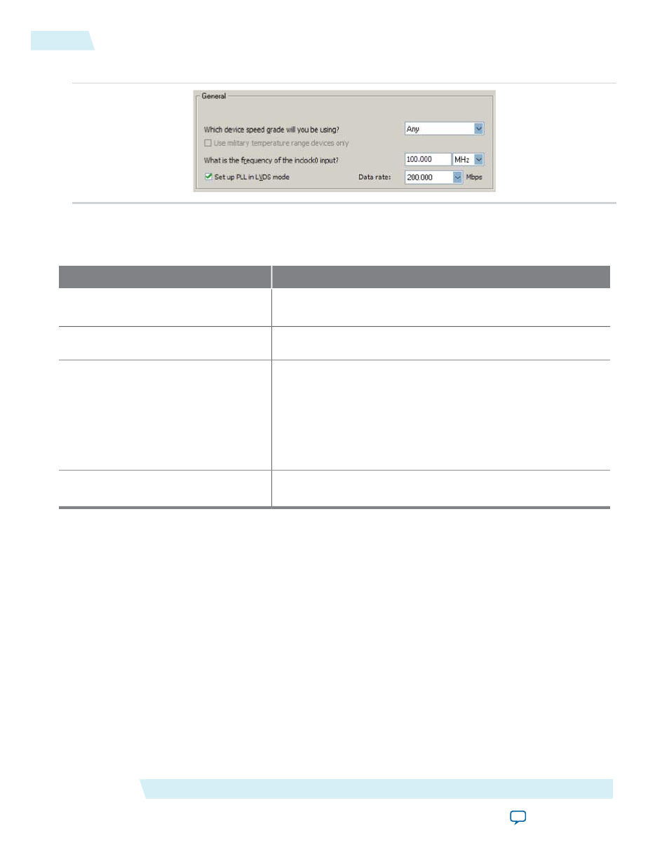
Figure 3: General Options
The following table lists the options you can select from the page.
Table 4: Operation Mode Options and Descriptions
Description
Option
Specify the speed grade if you are not already using a device with
the fastest speed. The lower the number, the faster the speed grade.
Which device speed grade will you be
using?
Specify the frequency of the input clock signal.
What is the frequency of the inclock0
input?
Select this option when you want the PLL to supply the necessary
clocking signals to the LVDS transmitter or receiver. In this mode,
the PLL type and operation mode are forced to fast PLL and normal
mode, respectively. This option creates two new output ports
—
sclkout
and
enable
.
This option is available only for the Arria GX, Stratix II,
Stratix II GX, andHardCopy II device families.
Set up PLL in LVDS mode
Specify the data rate for the PLL in LVDS mode. This option is
available only if Set up PLL in LVDS mode is enabled.
Data rate
Determining the PLL Lock Range
The PLL lock range is the range between the minimum (Freq min lock parameter) and maximum (Freq min
lock parameter) input frequency values for which the PLL can achieve lock. The Quartus II software shows
these input frequency values in the PLL Summary report located under Resource Section of the Fitter folder
in the Compilation Report. Changing the input frequency may cause the PLL to lose lock, but while the
input clock remains within the minimum and maximum frequency specifications, the PLL is able to achieve
lock.
Expanding the PLL Lock Range
The Quartus II software does not necessarily pick values for the PLL parameters to maximize the lock range.
For example, you specify a 75 MHz input clock in the ALTPLL parameter editor, the actual PLL lock range
may be between 70 MHz to 90 MHz. If your application requires a lock range of 50 MHz to 100 MHz, the
default lock range of this PLL is insufficient.
For devices that support clock switchover in PLLs, you can use the ALTPLL parameter editor to maximize
the lock range.
ALTPLL (Phase-Locked Loop) IP Core User Guide
Altera Corporation
ug-altpll
Determining the PLL Lock Range
6
2014.08.18