Parameter settings – Altera ALTPLL (Phase-Locked Loop) IP Core User Manual
Page 27
Parameter Settings
The parameter settings to enable the dynamic phase configuration feature are located on the PLL
Reconfiguration page of the ALTPLL parameter editor.
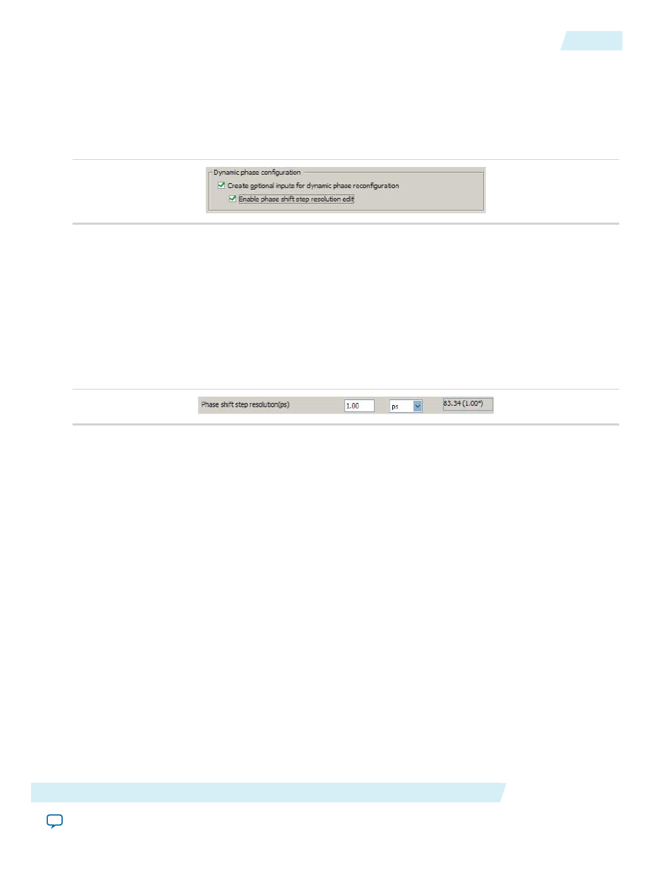
The following figure shows the dynamic phase configuration options.
Figure 18: Dynamic Phase Configuration
Turning on Create optional inputs for dynamic phase reconfiguration enables the feature, and create
these ports -
phasecounterselect[3..0]
,
phaseupdown
,
phasestep
,
scanclk
, and
phasedone
.
Turning on Enable phase shift step resolution edit allows you to modify the phase shift step resolution
value for each individual PLL output clock on its Output Clocks page.
The following figure shows the new option that appears on each output clock settings page. By default, the
finest phase shift resolution value is 1/8th of the VCO period. If the VCO frequency is at the lower end of
the supported VCO range, the phase shift resolution might be larger than you would prefer for your design.
Use this option to fine tune the phase shift step resolution.
Figure 19: Phase Shift Step Configuration
Modifying the PLL Phase Shift Step Resolution Using Advanced Parameters
The finest phase shift step resolution you can get in the ALTPLL IP core is 1/8th of the VCO period. If the
VCO frequency is at the lower end of the supported VCO range, the phase shift step resolution may be larger
than you would prefer for your design.
You can modify your phase shift resolution using the dynamic phase reconfiguration feature of the PLL. If
you want to modify the phase shift resolution without the dynamic phase reconfiguration feature enabled,
perform the following steps:
1. Create an ALTPLL instance. Make sure you specify the speed grade of your target device and the PLL
type.
2. On the PLL Reconfiguration page, turn on Create Optional Inputs for Dynamic Phase Reconfiguration
and Enable Phase Shift Step Resolution Edit.
3. On the Output Clocks page, set your desired phase shift for each required output clock. Click More
Details to see the internal PLL settings. Note all of the settings shown.
4. On the Bandwidth/SS page, click More Details to see the internal PLL settings. Note all of the settings
shown.
5. On the Inputs/Lock page, turn on Create output file(s) using the ‘Advanced’ PLL Parameters.
6. Return to the PLL Reconfiguration page and turn off Create Optional Inputs for Dynamic Phase
Reconfiguration.
7. Click Finish to generate the PLL instantiation file(s).
Altera Corporation
ALTPLL (Phase-Locked Loop) IP Core User Guide
27
Parameter Settings
ug-altpll
2014.08.18