Altera ALTPLL (Phase-Locked Loop) IP Core User Manual
Page 44
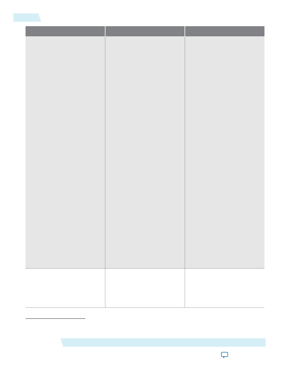
Description
Condition
Port Name
(7)
This output port acts as an
indicator when the PLL has
reached phase-locked. The
locked
port stays high as long as the PLL
is locked, and stays low when the
PLL is out-of-lock.
The number of cycles needed to
gate the
locked
signal is based on
the PLL input clock. The gated-
lock circuitry is clocked by the
PLL input clock. The maximum
lock time for the PLL is provided
in the DC and Switching
Characteristics chapter of the
device handbook.
Take the maximum lock time of
the PLL and divide it by the period
of the PLL input clock. The result
is the number of clock cycles
needed to gate the
locked
signal.
The lock signal is an asynchronous
output of the PLL. The PLL lock
signal is derived from the
reference clock and feedback clock
feeding the Phase Frequency
Detector (PFD).
Reference clock = Input Clock/N
Feedback clock = VCO/M
The PLL asserts the
locked
port
when the phases and frequencies
of the reference clock and
feedback clock are the same or
within the lock circuit tolerance.
When the difference between the
two clock signals goes beyond the
lock circuit tolerance, the PLL
loses lock.
Optional
locked
This output port indicates that
dynamic phase reconfiguration is
completed. Only available for
Arria II GX, Cyclone III,
HardCopy III onwards, and
Stratix III onwards.
Optional
phasedone
(7)
Replace the brackets,
[]
, in the port name with an integer to get the exact name (for example,
c0
,
c1
,
c3
,
e0
,
e1
,
e2
,
enable1
and
sclkout0
).
ALTPLL (Phase-Locked Loop) IP Core User Guide
Altera Corporation
ug-altpll
ALTPLL Output Ports
44
2014.08.18